


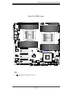

Chapter 5: Advanced Serverboard Setup
5-21
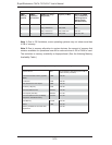
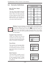
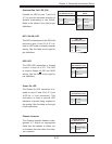
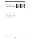
Overheat/Fan Fail LED (OH)
Connect an LED to pins 7 and 8 of
JF1 to provide advanced warning of
chassis overheating or fan failure.
Refer to the table on the right for pin
defi nitions.
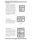
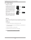
HDD LED
The HDD LED connection is located
on pins 13 and 14 of JF1. This LED
is used to display all IDE and SATA
activity. See the table on the right for
pin defi nitions.
OH/Fan Fail LED
Pin Defi nitions (JF1)
Pin# Defi nition
7 Vcc
8 Ground
HDD LED
Pin Defi nitions (JF1)
Pin# Defi nition
13 Vcc
14 HD Active
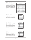
NIC1 LED
Pin Defi nitions (JF1)
Pin# Defi nition
11 Vcc
12 Ground
NIC1 (GLAN) LED
The LED connections for the GB LAN
port are on pins 11 and 12 of JF1. At-
tach an LED cable to display network
activity. See the table on the right for
pin defi nitions.
OH/Fan Fail Indicator
Status
State Defi nition
Off Normal
On Overheat
Flash-
ing
Fan Fail
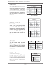
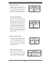
Power On LED
The Power On LED connector is lo-
cated on pins 15 and 16 of JF1 (use
JLED for a 3-pin connector). This
connection is used to provide LED
indication of power being supplied to
the system. See the table on the right
for pin defi nitions.
Power LED
Pin Defi nitions (JF1)
Pin# Defi nition
15 5V Stby
16 Control
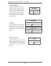
Chassis Intrusion
The Chassis Intrusion header is des-
ignated JL1. Attach an appropriate
cable from the chassis to inform you
of a chassis intrusion when the chas-
sis is opened
Chassis Intrusion
Pin Defi nitions (JL1)
Pin# Defi nition
1 Intrusion Input
2 Ground