


5-22
SuperWorkstation 7047A-73/7047A-T User's Manual
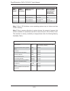
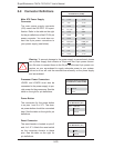
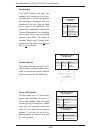
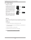
Fan Headers
The X9DA7/X9DAi has eight fan
headers, all of which are 4-pin fans.
However, pins 1-3 of the fan headers
are backward compatible with the
traditional 3-pin fans. See the table
on the right for pin defi nitions. The
onboard fan speeds are controlled by
Thermal Management (via Hardware
Monitoring) under the Advanced
Section in the BIOS. The default is
disabled. When using Thermal Man-
agement setting, please use all 3-pin
fans or all 4-pin fans.
Fan Header
Pin Defi nitions
(FAN1-8)
Pin# Defi nition
1 Ground (Black)
2 +12V (Red)
3 Tachometer
4 PWM Control
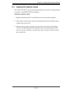
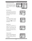
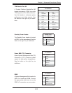
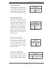
Power LED/Speaker
On JD1 header, pins 1-3 are used for
power LED indication, and pins 4-7
are for the speaker. See the tables
on the right for pin defi nitions. Please
note that the speaker connector
pins (4-7) are used with an external
speaker. If you wish to use the on-
board speaker, you should close pins
6-7 with a jumper.
Speaker Connector
Pin Settings
Pin Setting Defi nition
Pins 4-7 External Speaker
Pins 6-7 Internal Speaker
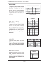
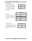
Internal Speaker
The Internal Speaker, located at SP1,
can be used to provide audible indica-
tions for various beep codes. See the
table on the right for pin defi nitions.
Internal Buzzer (SP1)
Pin Defi nition
Pin# Defi nitions
Pin 1 Pos. (+) Beep In
Pin 2 Neg. (-) Alarm
Speaker
PWR LED Connector
Pin Defi nitions
Pin Setting Defi nition
Pin 1 Anode (+)
Pin2 Cathode (-)
Pin3 NA