


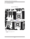
Chapter 5: Advanced Serverboard Setup
5-11
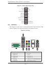
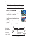
Memory Support
The X9DA7/X9DAi supports up to 512 GB of registered/unbuffered load reducing
ECC DDR3-1600/1333/1066/833 memory in 16 DIMM slots. For the latest memory
updates, please refer to the product page on the Supermicro website.
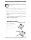
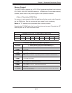
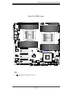
Order of Populating DIMM Slots
For memory to work properly, follow the table below for the correct order of populat-
ing the DIMM slots. See the serverboad layout page for slot numbering.
Notes: an "X" indicates a slot populated with a memory module.
Populate the "A" DIMM slots fi rst. Any of the slots may be used. Populate the "B"
slots only after all "A" slots have been fi lled.
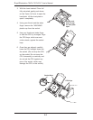
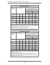
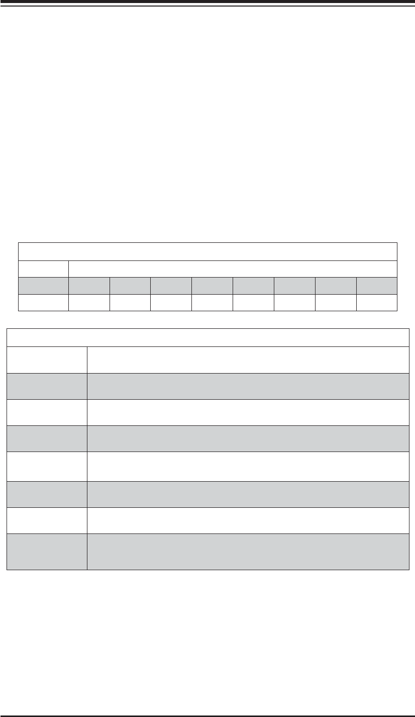
Processors and their Corresponding DIMM Slots
CPU# Corresponding DIMM Modules
CPU 1 P1-A1 P1-B1 P1-C1 P1-D1 P1-A2 P1-B2 P1-C2 P1-D2
CPU 2 P2-E1 P2-F1 P2-G1 P4-H1 P2-E2 P2-F2 P2-G2 P2-H2
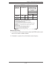
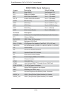
Processor and Memory Module Population
Number of
CPUs+DIMMs
CPU and Memory Population Confi guration Table
(For memory to work proper, please install DIMMs in pairs.)
1 CPU &
2 DIMMs
CPU1
P1-A1/P1-B1
1 CPU &
4 DIMMs
CPU1
P1-A1/P1-B1, P1-C1/P1-D1
1 CPU &
5~8 DIMMs
CPU1
P1-A1/P1-B1, P1-C1/P1-D1 + Any memory pairs in P1-A2/-B2/-C2/-D2 DIMM slots
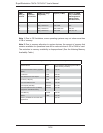
2 CPUs &
4 DIMMs
CPU1 + CPU2
P1-A1/P1-B1, P2-E1/P2-F1
2 CPUs &
6 DIMMs
CPU1 + CPU2
P1-A1/P1-B1/ P1-C1, P2-E1/P2-F1/P2-G1
2 CPUs &
8 DIMMs
CPU1 + CPU2
P1-A1/P1-B1/ P1-C1/P1-D1, P2-E1/P2-F1/P2-G1/P2-H1
2 CPUs &
10~16 DIMMs
CPU1/CPU2
P1-A1/P1-B1/ P1-C1/P1-D1/P1-A2, P2-E1/P2-F1/P2-G1/P2-H1+/P2-E2, Any memory
pairs in P1, P2 DIMM slots