


5-20
SuperWorkstation 7047A-73/7047A-T User's Manual
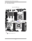
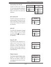
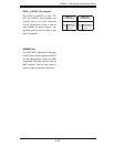
Reset Connector
The reset header is located on pins 3
and 4 of JF1. Attach the reset switch
on the computer chassis to these
pins. See the table on the right for
pin defi nitions.
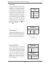
Power Button
The connection for the power button
is on pins 1 and 2 of JF1. The chas-
sis power button should be connected
here. See the table on the right for pin
defi nitions.
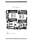
5-9 Connector Defi nitions
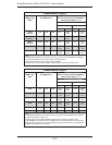
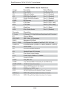
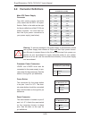
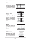
Main ATX Power Connector
Pin Defi nitions (JPW3)
Pin# Defi nition Pin # Defi nition
13 +3.3V 1 +3.3V
14 -12V 2 +3.3V
15 COM 3 COM
16 PS_ON 4 +5V
17 COM 5 COM
18 COM 6 +5V
19 COM 7 COM
20 Res (NC) 8 PWR_OK
21 +5V 9 5VSB
22 +5V 10 +12V
23 +5V 11 +12V
24 COM 12 +3.3V
Reset Button
Pin Defi nitions (JF1)
Pin# Defi nition
3 Reset
4 Ground
Power Button
Pin Defi nitions (JF1)
Pin# Defi nition
1 PW_ON
2 Ground
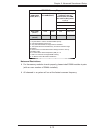
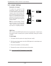
Main ATX Power Supply
Connector
The main power supply connector
(J22) meets the SSI EPS 12V speci-
fi cation. Refer to the table on the right
for the pin defi nitions of the ATX 24-pin
power connector. You must also con-
nect the 8-pin power connectors to
your power supply (see below).
Required Connection
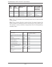
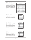
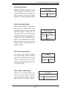
Processor Power Connectors
Pin Defi nitions (JPW1/JPW2)
Pins Defi nition
1 - 4 Ground
5 - 8 +12V
Processor Power Connectors
JPWR1 and JPWR2 must also be
connected to the power supply to pro-
vide power for the processors. See the
table on the right for pin defi nitions.
Warning: To prevent damage to the power supply or serverboard, please
use a power supply that contains a 24-pin and two 8-pin power connec-
tors. Be sure to connect these to the 24-pin and the two 8-pin power con-
nectors on your serverboard to supply adequate power to your system.
Failure to do so will void the manufacturer warranty on the power supply
and serverboard.
!