


2-8
X6DH3-G2/X6DHi-G2 User's Manual
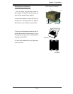
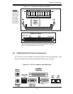
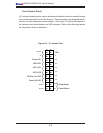
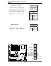
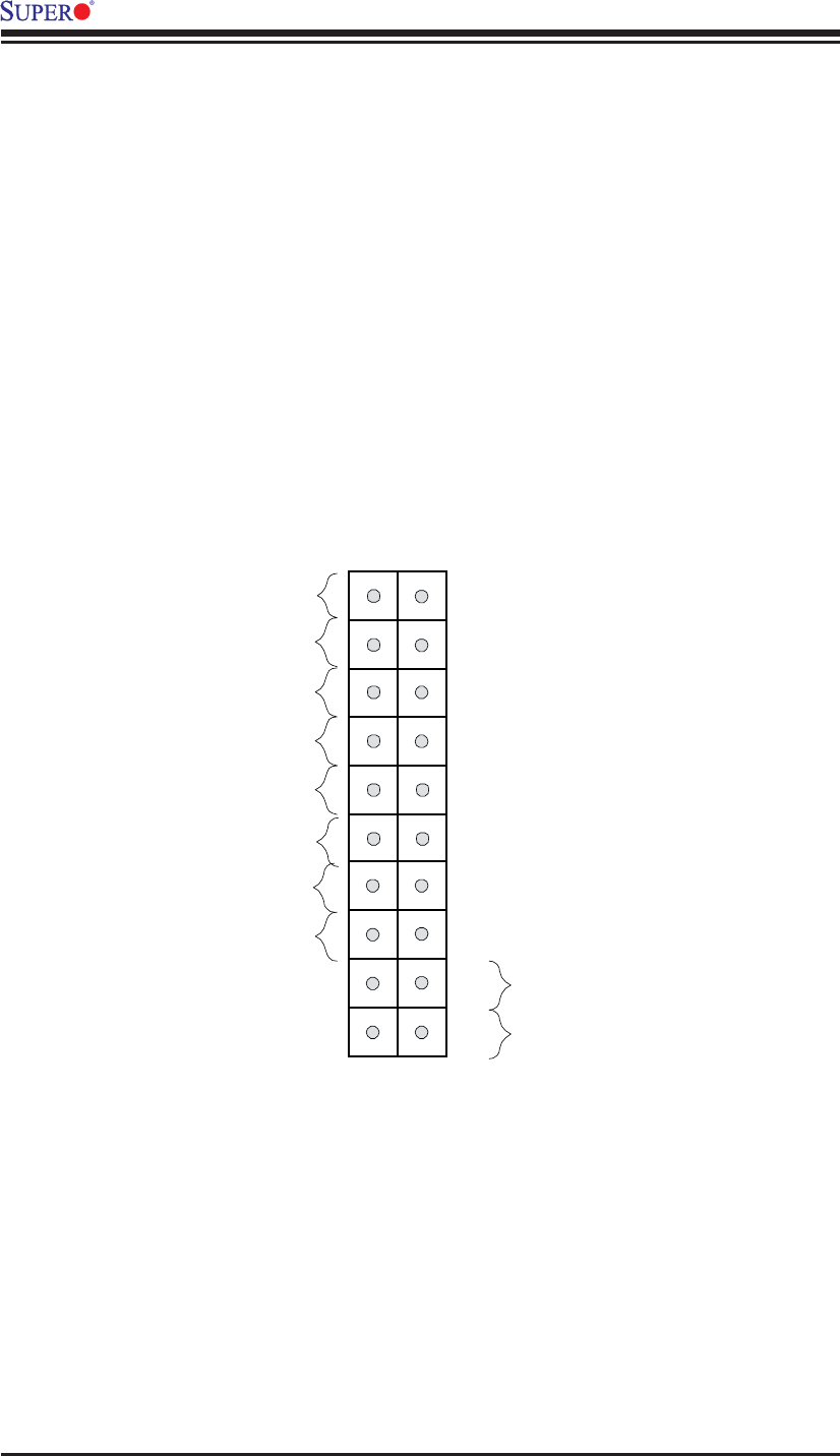
Front Control Panel
JF1 contains header pins for various buttons and indicators that are normally located
on a control panel at the front of the chassis. These connectors are designed specifi -
cally for use with Supermicro server chassis. See Figure 2-4 for the descriptions of
the various control panel buttons and LED indicators. Refer to the following section
for descriptions and pin defi nitions.
Figure 2-4. JF1 Header Pins
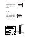
Power Button
OH/Fan Fail LED
1
NIC1 LED
Reset Button
2
Power Fail LED
HDD LED
Power LED
Reset
Pwr
Vcc
Vcc
Vcc
Vcc
Ground
Ground
1920
Vcc
X
Ground
NMI
X
Vcc
NIC2 LED