


Chapter 2: Installation
2-21
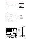
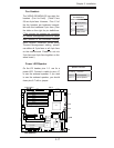
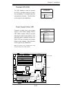
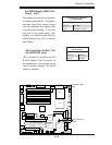
Overheat LED (JOH)
The JOH header is used to connect
an LED to provide warning of chas-
sis overheating. It is located near the
microphone connector. See the table
on the right for pin defi nitions.
Note: This feature is only available when using
redundant Supermicro power supplies.
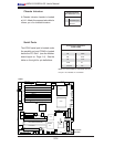
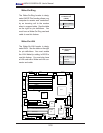
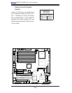
Power Supply Failure LED
Connect a cable from your power
supply to the Power Supply Failure
LED (PSF) header (JP9) to provide
warning of power supply failure. This
warning signal is passed through the
PWR_LED pin to indicate of a power
failure on the chassis. See the table
on the right for pin defi nitions.
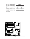
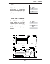
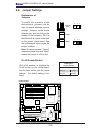
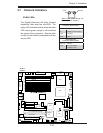
PS Fail LED
OH LED
LAN1
®
JLAN1
S
UPER X6
DH3-G2
LAN2
DIM
M 2
A
DIMM 2B
DIMM 3
A
DIMM 3B
DIMM 4A
DIMM 4B
DIMM 1B
DIMM 1
A
12V 8-pin
PWR
JF
1
FP Control
JOH
IPMI
ID
E2
Flo
ppy
BIOS
Fan4
SMB
PCI-
X100
MH
z
PCI-X 1
00 MHz
Z
C
R (Gr
een
Slot)
PCI-
X 133 MHz
B
attery
JPL1
PCI-
E X8
VGA
COM1
USB
0/1
KB
/
MS
Fan6
Fan5
ATX PWR
12V
4-Pin
PWR
Parrallel
Port
24-Pin
Fan7
JPW1
F
an8
C
PU1
S I/O
PSF
Fan3
ID
E
1
PC
I-33 MH
z
U
SB2/
3
ICH
J
PG
1
J
WD
Slot1
Slot2
Slo
t3
Slot4
Slot5
Slot6
PCI-
E X8
G
LAN
CTRL
6
300ESB
Buzzer
P
XH
JBT1
I-S
AT
A1
G
LAN
CTRL
JPL2
JL1
J
P
S1
SAS
C
TRL
Fan2
Fan1
J
AR
J
3P
CPU2
E7520
Bank1
Bank2
Bank3
Bank4
WOL
SEP
C
COM2
SMB PS
JWOR
JS1
0
VGA
C
T
RL
JD1
JI
2
C2
I-SATA0
DS5
DS6
DS7
DS8
DS1
DS2
DS3
DS4
SAS4-7
SAS0-3
JSM1
JS
9
JP9
J1D1
J32
J
38
J33
J14
J7
JLAN1
JLAN2
JI
2
C1
J31
JSM2
JP1
Overheat LED
Pin Defi nitions
Pin# Defi nition
1 5vDC
2 OH Active
PWR Supply Fail LED
Pin Defi nitions
Pin# Defi nition
1 PWR 1: Fail
2 PWR 2: Fail
3 PWR 3: Fail
4 Signal: Alarm Reset