


Chapter 2: Installation
2-17
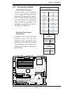
LAN1
®
JLAN1
S
UPER X6DH3-G2
LAN2
DIM
M 2A
DIMM 2B
DIMM 3A
DIMM 3B
DIM
M 4A
DIM
M 4B
DIMM 1B
DIMM 1
A
12V 8-pin
PWR
JF
1
FP Control
JOH
IPMI
IDE2
Floppy
BIOS
Fan4
SMB
P
CI-X100
M
Hz
P
CI-X 100 M
Hz
ZCR (G
reen Slo
t)
P
CI-X
13
3 MHz
B
a
ttery
JPL1
P
CI-E X
8
VGA
COM1
U
SB
0/1
KB/M
S
F
an6
F
an5
A
T
X PWR
12V
4-Pin
PWR
Parrallel
Port
24-Pin
Fan
7
JPW1
F
an8
CPU1
S
I/O
PSF
F
an3
IDE1
P
CI-33 MHz
U
S
B2/3
I
CH
J
P
G
1
JWD
Slot1
Slot2
Slot3
Slot4
Slot5
Slo
t6
P
CI-E X8
G
LAN
C
T
RL
6
300
ESB
B
u
zze
r
P
X
H
JB
T1
I-
SATA1
GLAN
C
T
RL
JPL2
JL1
J
PS1
SAS
C
T
RL
Fan2
F
a
n1
JAR
J
3P
CPU2
E75
20
Bank1
Bank2
Bank3
Bank4
WOL
SEP
C
COM2
SMB PS
J
WOR
JS10
V
GA
CTRL
JD1
JI
2
C2
I-SATA0
DS5
DS6
DS7
DS8
DS1
DS2
DS3
DS4
SAS4-7
SAS0-3
JSM1
JS
9
J
P
9
J
1D1
J
32
J
38
J
33
J
14
J
7
J
LAN1
J
LAN2
JI
2
C
1
J31
JSM2
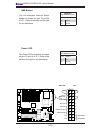
JP1
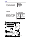
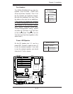
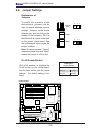
Power LED/Speaker
On the JDI header, pins 1-3 are for a
power LED. Connect a cable to pins 4-7
to use the external speaker. If you wish
to use the onboard speaker, you should
close pins 6-7 with a jumper.
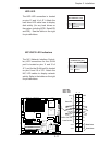
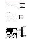
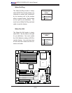
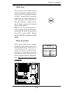
Fan Headers
The X6DH3-G2/X6DHi-G2 has eight fan
headers (Fan1 to Fan8). (*Note: Fans
5-8 are 4-pin fans. However, Pins 1-3 of
the fan headers are backward compat-
ible with the traditional 3-pin fans.) See
the table on the right for pin defi nitions.
(*The onboard fan speeds are controlled
by Thermal Management via BIOS--Hard-
ware Monitor in the Advanced Setting
.
Note: Default: Disabled, When using
Thermal Management setting, please
use either all 3-pin fans or all 4-pin fans
on the motherboard. Please do not mix
3-pin fans and 4-pin fans together on the
same board.)
PWR LED/SPKR
Fan 7
Fan 5
Fan 6
Fan 1
Fan 2
Fan 3
Fan4
Fan8
Fan Header
Pin Defi nitions
Pin# Defi nition
1 Ground (Black)
2 +12V (Red)
3 Tachometer
4 PWM_Control
Speaker Connector
Pin Setting Defi nition
Pins 6-7 Internal Speaker
Pins 4-7 External Speaker