


Chapter 2: Installation
2-9
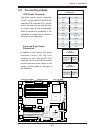
LAN1
®
JLAN1
S
UPER X6DH3-G2
LAN2
DIMM 2
A
DIMM 2B
DIMM 3A
DIMM 3
B
DIM
M 4A
DIMM 4B
DIMM 1B
DIM
M 1A
12V 8-pin
PWR
JF
1
FP Control
JOH
IPM
I
ID
E2
Flo
pp
y
BIOS
Fan4
SMB
PCI-X1
00 MHz
PCI-X 100 MH
z
Z
CR (Green Slot)
PCI-X 133 MH
z
Ba
ttery
JPL1
P
C
I-E
X8
V
GA
COM1
US
B
0/
1
K
B
/
M
S
Fan6
Fan5
ATX
PWR
12V 4-P
in
PWR
Parrallel
Port
24-Pin
Fan
7
JPW1
Fan8
C
PU1
S I/O
PSF
Fan3
IDE1
P
C
I-3
3 M
Hz
U
S
B2/3
ICH
JPG1
J
WD
Slot1
Slot2
Slot3
Slot4
Slo
t5
Slo
t6
PCI-E X8
GLAN
CTRL
6300ESB
Buzze
r
PXH
JBT1
I-SAT
A1
G
LAN
CTRL
JPL2
J
L1
JP
S
1
S
A
S
CTRL
Fa
n2
F
an1
J
AR
J
3P
CPU2
E
7520
Bank1
Bank2
Bank3
Bank4
WOL
SEPC
COM2
S
MB PS
JWOR
JS
1
0
VGA
C
T
RL
JD1
J
I
2
C2
I-SAT
A0
DS5
DS6
DS7
DS8
DS1
DS2
DS3
DS4
SAS4-7
SAS0-3
JSM1
JS
9
JP
9
J
1D1
J32
J38
J33
J14
J7
JLAN1
J
LAN2
J
I
2
C1
J31
JSM2
JP1
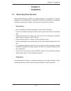
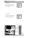
2-5 Connecting Cables
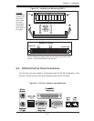
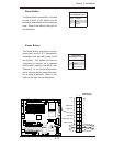
ATX Power Connector
The main power supply connector
(JPW1) on the X6DH3-G2/X6DHi-G2
meets the SSI (Superset ATX) specifi -
cation. You can only use a 24-pin pow-
er supply cable on the motherboard.
Make sure that the orientation of the
connector is correct. See the table on
the right for pin defi nitions.
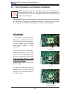
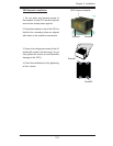
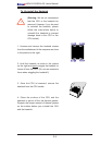
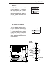
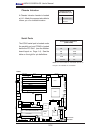
4-pin and 8-pin Power
Connectors
In addition to the Primary ATX power
connector (above), the 12V 8-pin
connector at J1D1 and the 12V 4-pin
connector at J38 must also be used to
provide adequate power supply to the
system. See the tables on the right for
pin defi nitions.
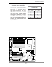
24-Pin ATX PWR 8-Pin 12V PWR4-Pin12V CPU PWR
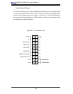
ATX Power 24-pin Connector
Pin Defi nitions
Pin# Defi nition Pin # Defi nition
13 +3.3V 1 +3.3V
14 -12V 2 +3.3V
15 COM 3 COM
16 PS_ON 4 +5V
17 COM 5 COM
18 COM 6 +5V
19 COM 7 COM
20 Res (NC) 8 PWR_OK
21 +5V 9 5VSB
22 +5V 10 +12V
23 +5V 11 +12V
24 COM 12 +3.3V
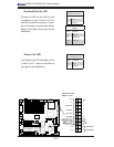
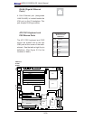
12V 8-pin Power Con-
nector
Pin Defi nitions
Pins Defi nition
1 through 4 Ground
5 through 8 +12V
12V 4-pin Power Con-
nector
Pin Defi nitions
Pins Defi nition
1 and 2 Ground
3 and 3 +12V