


Chapter 2: Installation
2-11
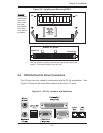
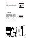
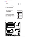
Power Button
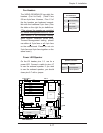
OH/Fan Fail LED
1
NIC1 LED
Reset Button
2
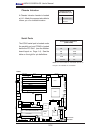
Power Fail LED
HDD LED
Power LED
Reset
Pwr
Vcc
Vcc
Vcc
Vcc
Ground
Ground
1920
Vcc
X
Ground
NMI
X
Vcc
NIC2 LED
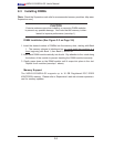
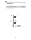
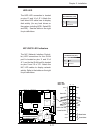
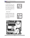
NIC1/NIC2 LED Indicators
The NIC (Network Interface Control-
ler) LED connections for the GLAN
port1 is located on pins 11 and 12 of
JF1, and for the GLAN port2 is located
on pins 9 and 10 of JF1. Attach the
NIC LED cables to display network
activity. Refer to the tables on the right
for pin defi nitions.
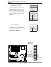
HDD LED
The HDD LED connection is located
on pins 13 and 14 of JF1. Attach the
hard drive LED cable here to display
disk activity (for any hard drives on
the system, including SCSI, Serial ATA
and IDE). See the table on the right
for pin defi nitions.
NIC1 LED
NIC2 LED
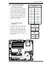
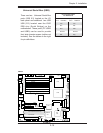
LAN1
®
JLAN1
S
UPER X6DH3-G2
LAN2
DIMM 2A
DIM
M 2B
DIM
M 3A
DIMM 3
B
DIMM 4A
DIMM 4B
DIMM 1B
DIMM 1A
12V 8-pin
PWR
JF
1
FP Control
JOH
IPMI
IDE2
Flo
pp
y
BIOS
Fan4
S
MB
P
CI-
X1
00
MHz
PCI-
X
1
00 MHz
Z
CR
(Green
Slot
)
PCI-
X 133 M
Hz
Battery
JPL1
PCI-
E
X8
VGA
COM1
USB
0
/1
KB/MS
Fa
n
6
Fa
n
5
ATX PWR
12V 4-Pin
PWR
Parrallel
Port
24-Pin
F
an
7
JPW1
F
an8
C
P
U1
S I/O
PSF
F
an3
ID
E1
PCI-33 M
Hz
U
S
B2/3
ICH
J
P
G1
J
WD
Slo
t1
Slot2
Slot3
Slot4
Slot5
Slot6
P
C
I-E
X
8
GLAN
CTRL
6300ES
B
B
uzzer
PXH
J
B
T1
I-S
AT
A1
G
LAN
CTRL
JPL2
J
L1
J
PS
1
SAS
CT
RL
Fan2
F
an1
JAR
J
3P
CPU2
E
752
0
Bank1
Bank2
Bank3
Bank4
WOL
SE
PC
COM2
SMB PS
JW
OR
JS10
V
GA
C
TRL
JD1
JI
2
C
2
I-S
A
T
A
0
DS5
DS6
DS7
DS8
DS1
DS2
D
S3
DS4
SAS4-7
SAS0-3
JSM1
JS9
J
P9
J
1D1
J
32
J
38
J
33
J
14
J
7
J
LAN1
J
LAN2
J
I
2
C
1
J31
JSM2
JP1
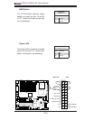
HDD LED
GLAN1/2 LED
Pin Defi nitions (JF1)
Pin# Defi nition
9/11 Vcc
11/12 Ground
HDD LED
Pin Defi nitions (JF1)
Pin# Defi nition
13 +5V
14 HD Active