


Chapter 2: Installation
2-25
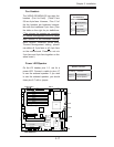
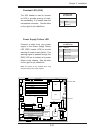
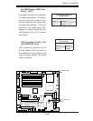
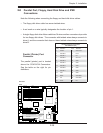
3rd PWR Supply PWR Fault
Detect (J3P)
The system can notify you in the event
of a power supply failure. This feature
assumes that three power supply
units are installed in the chassis, with
one acting as a backup. If you only
have one or two power supply units
installed, you should disable this (the
default setting) with J3P to prevent
false alarms.
3rd PWR Fault
Detect
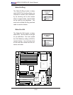
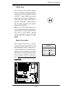
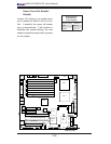
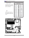
SAS Controller Enable (*For
the X6DH3-G2 only)
JPS1 enables or disables the AIC
9140W Adaptec SAS Controller on
the motherboard. See the table on the
right for jumper settings. The default
setting is enabled.
SAS Controller
Enable
LAN1
®
JLAN1
S
UPER X6DH3-G2
LAN2
DIMM 2
A
DIMM 2B
DIMM 3A
DIMM 3B
DIMM 4A
DIMM 4B
DIM
M 1B
DIM
M 1A
12V 8-pin
PWR
JF
1
FP Control
JOH
IPMI
IDE
2
Floppy
BI
OS
Fan4
SMB
PC
I-X1
00
MHz
PC
I-X 1
00
MH
z ZC
R (Green Slo
t)
PCI-
X
13
3 MHz
Battery
JPL1
PCI-E X8
V
GA
COM1
USB
0/1
KB/MS
Fan6
Fan5
A
TX PWR
12V 4-Pin
PWR
Parrallel
Port
24-P
in
Fan7
JPW1
Fan8
CPU1
S
I
/
O
PSF
F
a
n3
IDE1
P
C
I-33 MHz
U
SB2/3
ICH
JPG1
J
WD
Slo
t1
Slo
t2
Slo
t3
Slo
t4
Slot5
Slo
t6
PCI-E X8
GLAN
CTRL
6
300ES
B
Buzzer
PXH
JBT1
I-S
AT
A1
GLAN
CTRL
JPL2
J
L1
JPS
1
SA
S
CTRL
Fan2
F
a
n1
JAR
J3P
C
PU2
E7520
Bank1
Bank2
Bank3
Bank4
WOL
SE
PC
COM2
SMB PS
JWOR
JS10
VGA
C
TRL
JD1
JI
2
C
2
I-SATA0
DS5
DS6
DS7
DS8
DS1
DS2
DS3
DS4
SAS4-7
SAS0-3
JSM1
JS9
JP9
J
1D1
J32
J38
J
33
J14
J
7
JLAN1
JLAN2
JI
2
C
1
J31
JSM2
JP1
3rd PWR Supply PWR Fault
Jumper Settings
Jumper Setting Defi nition
Closed Enabled
Open Disabled (*Default)
SAS Controller Enable
Jumper Settings
Jumper Setting Defi nition
Pins 1-2 Enabled
Pins 2-3 Disabled