


Chapter 2: Overview
2-5
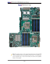
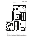
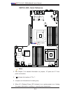
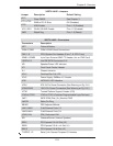
X8DTU-LN4F+ Jumpers
Jumper
Description Default Setting
JBT1
Clear CMOS See Chapter 3
JI
2
C1/JI
2
C2
SMB to PCI-E Slots Off (Disabled)
JPG1
VGA Enable Pins 1~2 (Enabled)
JPL1/JPL2 GLAN1/GLAN2 Enable Pins 1-2 (Enabled)
JWD Watch Dog Pins 1~2 (Reset)
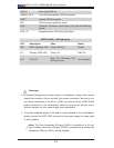
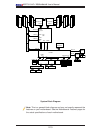
X8DTU-LN4F+ Connectors
Connectors Description
JBT1 Onboard Battery
COM1/COM2 COM1/COM2 Serial Connections
FAN 1~8 CPU//System Fan Headers (Fans 7, 8: CPU Fans)
IPMB1/JIPMB2 4-pin/3-pin External BMC I
2
C Header (for an IPMI Card)
I-SATA 0~5 Intel SB SATA Connectors 0~5
JD1 Speaker/Power LED Indicator
JF1 Front Panel Control Header
JL1 Chassis Intrusion
JOH1 Overheat/Fan Fail LED
JPI
2
C Power Supply SMBbus I
2
C Header
JPK1 NIC3/NIC4 LED Headers
JPW1 ATX 24-Pin Power Connector (See Warning on Pg. 2-6.)
JPW2/JPW3 12V 8-Pin Power Connectors (See Warning on Pg. 2-6.)
JPTM Trusted Platform Support Header (JP8)
JTAG of CPLD JTAG of CPLD (Complex Programmable Logic Devices)
JWF1 SATA DOM (Disk_On_Module) PWR
JWOR1 Wake-On-Ring
KB/MS PS2 Keyboard/Mouse
LAN1/LAN2 G-bit Ethernet Ports 1/2
LAN3/LAN4 G-bit Ethernet Ports 3/4
(IPMI) LAN IPMI_Dedicated LAN
SP1 Onboard Buzzer (Internal Speaker)
SXB1 PCI-Express 2.0 x16 Slot (J2)
SXB2 PCI-Express 2.0 x8 + x4 Slot (J1)
SXB 3 PCI-Express 2.0 x8 Slot (J3)
T-SGPIO 1/2 Serial_Link General Purpose I/O Headers