


Chapter 3: Installation
3-23
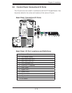
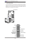
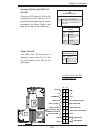
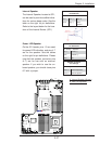
Power Button
Blue+ (OH/Fan Fail/
PWR FaiL/UID LED
1
NIC1 Link LED
Reset Button
2
Power Fail LED
HDD LED
FP PWRLED
Reset
PWR
3.3 V
ID_UID_SW/3/3V Stby
Red+ (Blue Led Cathode)
Ground
Ground
1920
3.3V
X
Ground
NMI
X
NIC2 Link LED
NIC2 Active LED
NIC1 Active LED
X8DTU-LN4F+
Rev. 2.0
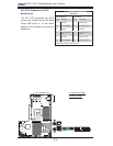
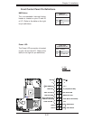
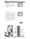
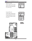
Power Fail LED
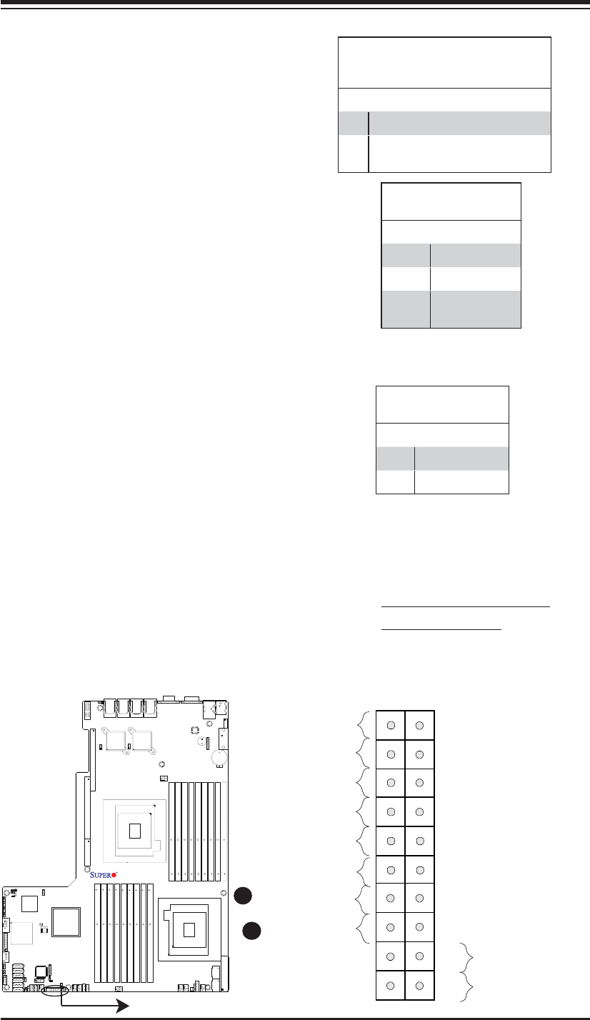
The Power Fail LED connection is
located on pins 5 and 6 of JF1. Re-
fer to the table on the right for pin
defi nitions.
PWR Fail LED
Pin Defi nitions (JF1)
Pin# Defi nition
5 3.3V
6 PWR Fail LED
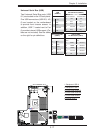
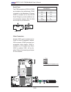
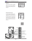
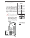
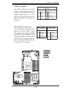
B
A. OH/Fan Fail & UID LEDs
B. PWR Supply Fail
Overheat (OH)/Fan Fail/PWR Fail/
UID LED
Connect an LED cable to OH/Fan Fail
connection on pins 7 and 8 of JF1 to
provide advanced warnings of chassis
overheat or fan failure. Refer to the
table on the right for pin defi nitions.
Blue+ (OH/Fan Fail/PWR Fail/UID
LED)
Pin Defi nitions (JF1)
Pin# Defi nition
7 Red+ (Blue LED Cathode)
8 Blue+ (OH/Fan Fail/PWR Fail/
UID LED)
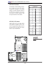
OH/Fan Fail Indicator
Status
State Defi nition
Off Normal
On Overheat
Flash-
ing
Fan Fail
A