


Chapter 3: Installation
3-25
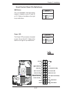
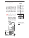
Warning! To avoid damaging the
power supply or motherboard, please
use a power supply that contains a
24-pin and two 8-pin power connec-
tors. Be sure to connect these con-
nectors to the 24-pin (JPW1) and the
two 8-pin (JPW2, JPW3) power con-
nectors on the motherboard. Failure
to do so will void the manufacturer
warranty on your power supply and
motherboard.
SP1
JF1
JD1
JWF1
JIPMB2
IPMB1
JP8
VGA2
JPK1
JPW1
JBT1
JPW3
JPW2
J3
J2
J1
JPL2
JPG1
JWD
FAN4
FAN5
FAN3
FAN2
FAN1
FAN6
JBT1
D20
LE11
JL1
JI2C1
JI2C2
JPI2C
USB7
USB4/5
USB2/3
Clear
COMS
JTPM
COM2
UIOP
UID
LAN4
LAN3
LAN2
LAN1
VGA1
COM1
FAN8/CPU1
FAN7/CPU2
CPU2
P1-DIMM2C
P1-DIMM1C
P1-DIMM3C
JTAG of CPLD
SXB1: PCI-E 2.0 x16
SXB3: PCI-E 2.0 x8
SXB2: PCI-E 2.0 x8+x4
P1-DIMM3B
P1-DIMM3A
P1-DIMM1A
P1-DIMM1B
P1-DIMM2B
P1-DIMM2A
CPU1
USB0/1
IPMI_LAN
P2-DIMM2C
P2-DIMM1C
P2-DIMM3C
P2-DIMM3B
P2-DIMM3A
P2-DIMM1A
P2-DIMM1B
P2-DIMM2B
P2-DIMM2A
JPL1
KB/MS
BIOS
FPCTRL
LE1
SATA0~5
LAN1
LAN2
IOH-36D
ICH10R
Intel
Intel
BMC
Winbond
PHY
USB6
T-SGPIO2
T-SGPIO1
X8DTU-LN4F+
JOH1
WOR1
Rev. 2.0
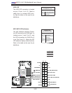
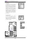
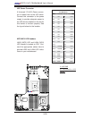
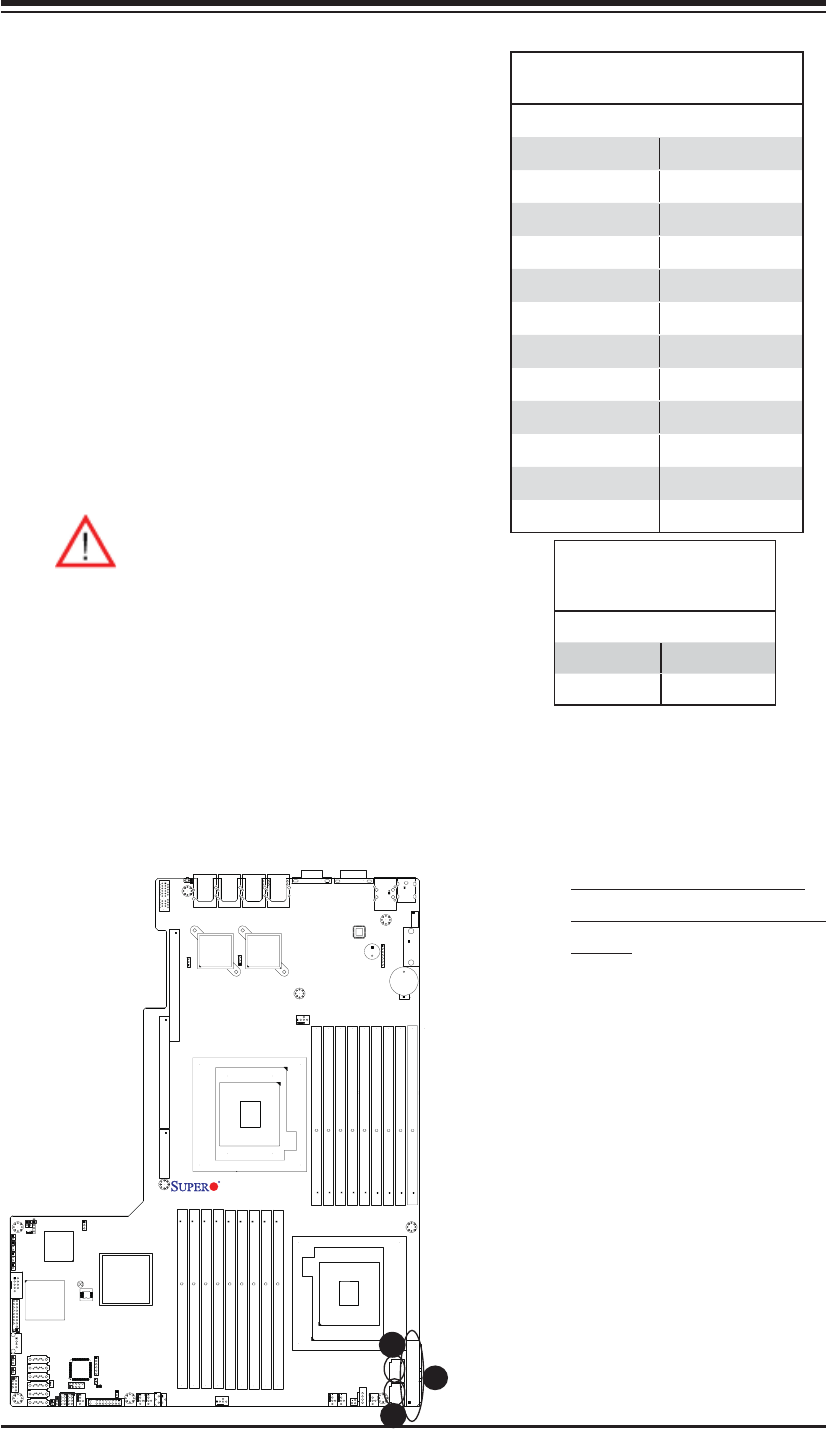
3-6 Connecting Cables
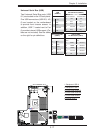
Power Connectors
A 24-pin main power supply connector (JPW1)
and two 8-pin CPU PWR connectors (JPW2/
JPW3) are located on the motherboard. These
power connectors meet the SSI EPS 12V
specifi cation. In addition to the 24-pin ATX
power connector, the 12V 8-pin CPU PWR
connectors at JPW2/JPW3 must also be con-
nected to your power supply. See the table on
the right for pin defi nitions.
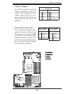
ATX Power 24-pin Connector
Pin Defi nitions
Pin# Defi nition Pin # Defi nition
13 +3.3V 1 +3.3V
14 -12V 2 +3.3V
15 COM 3 COM
16 PS_ON 4 +5V
17 COM 5 COM
18 COM 6 +5V
19 COM 7 COM
20 Res (NC) 8 PWR_OK
21 +5V 9 5VSB
22 +5V 10 +12V
23 +5V 11 +12V
24 COM 12 +3.3V
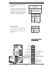
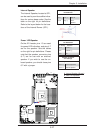
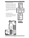
12V 8-pin PWR Con-
nector
Pin Defi nitions
Pins Defi nition
1 through 4 Ground
5 through 8 +12V
A. 24-pin ATX PWR (Req'd)
B/C.8-pin Processor PWR
(Req'd)
A
B
C
(Required)