


Chapter 3: Installation
3-21
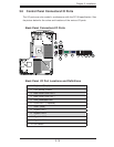
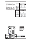
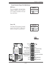
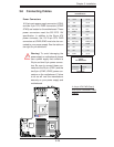
Power Button
Blue+ (OH/Fan Fail/
PWR FaiL/UID LED
1
NIC1 Link LED
Reset Button
2
Power Fail LED
HDD LED
FP PWRLED
Reset
PWR
3.3 V
ID_UID_SW/3/3V Stby
Red+ (Blue Led Cathode)
Ground
Ground
1920
3.3V
X
Ground
NMI
X
NIC2 Link LED
NIC2 Active LED
NIC1 Active LED
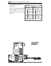
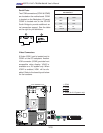
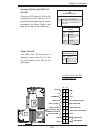
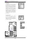
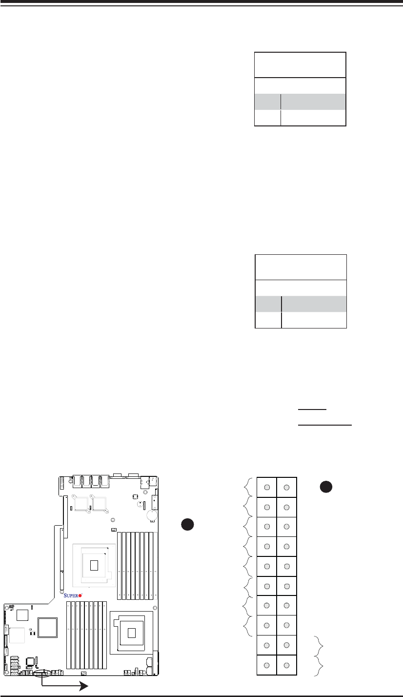
Power LED
The Power LED connection is located
on pins 15 and 16 of JF1. Refer to the
table on the right for pin defi nitions.
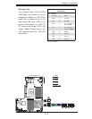
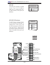
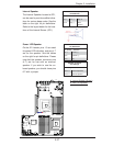
NMI Button
The non-maskable interrupt button
header is located on pins 19 and 20
of JF1. Refer to the table on the right
for pin defi nitions.
NMI Button
Pin Defi nitions (JF1)
Pin# Defi nition
19 NMI
20 Ground
Power LED
Pin Defi nitions (JF1)
Pin# Defi nition
15 3.3V
16 FP PWR LED
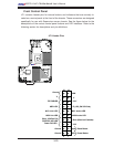
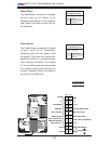
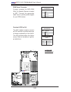
Front Control Panel Pin Defi nitions
A. NMI
B. PWR LED
A
B
X8DTU-LN4F+
Rev. 2.0