


3-22
X8DTU-LN4F+ Motherboard User's Manual
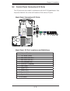
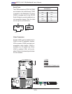
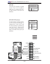
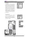
Power Button
Blue+ (OH/Fan Fail/
PWR FaiL/UID LED
1
NIC1 Link LED
Reset Button
2
Power Fail LED
HDD LED
FP PWRLED
Reset
PWR
3.3 V
ID_UID_SW/3/3V Stby
Red+ (Blue Led Cathode)
Ground
Ground
1920
3.3V
X
Ground
NMI
X
NIC2 Link LED
NIC2 Active LED
NIC1 Active LED
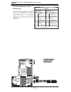
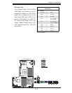
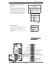
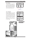
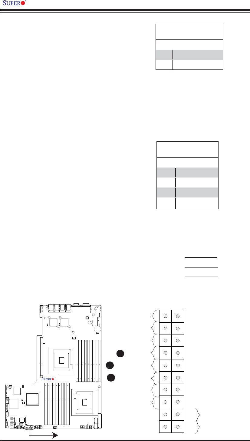
NIC1/NIC2 LED Indicators
The NIC (Network Interface Control-
ler) LED connection for GLAN port 1 is
located on pins 11 and 12 of JF1, and
the LED connection for GLAN Port 2
is on Pins 9 and 10. Attach the NIC
LED cables to display network activity.
Refer to the table on the right for pin
defi nitions.
GLAN1/2 LED
Pin Defi nitions (JF1)
Pin# Defi nition
9 NIC2 Active
10 NIC2 Link
11 NIC1 Active
12 NIC2 Link
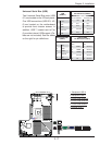
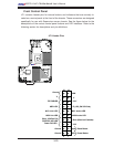
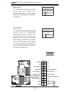
B
C
A. HDD LED
B. NIC1 LED
C. NIC2 LED
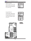
HDD LED
The HDD LED connection is located
on pins 13 and 14 of JF1. Attach a
cable here to indicate HDD activ-
ity. See the table on the right for pin
defi nitions.
HDD LED
Pin Defi nitions (JF1)
Pin# Defi nition
13 ID_UID_SW/3.3VSB
14 HDD Active
A
X8DTU-LN4F+
Rev. 2.0