


3-24
X8DTU-LN4F+ Motherboard User's Manual
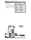
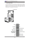
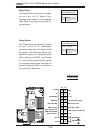
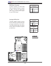
Power Button
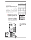
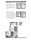
Blue+ (OH/Fan Fail/
PWR FaiL/UID LED
1
NIC1 Link LED
Reset Button
2
Power Fail LED
HDD LED
FP PWRLED
Reset
PWR
3.3 V
ID_UID_SW/3/3V Stby
Red+ (Blue Led Cathode)
Ground
Ground
1920
3.3V
X
Ground
NMI
X
NIC2 Link LED
NIC2 Active LED
NIC1 Active LED
Power Button
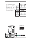
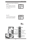
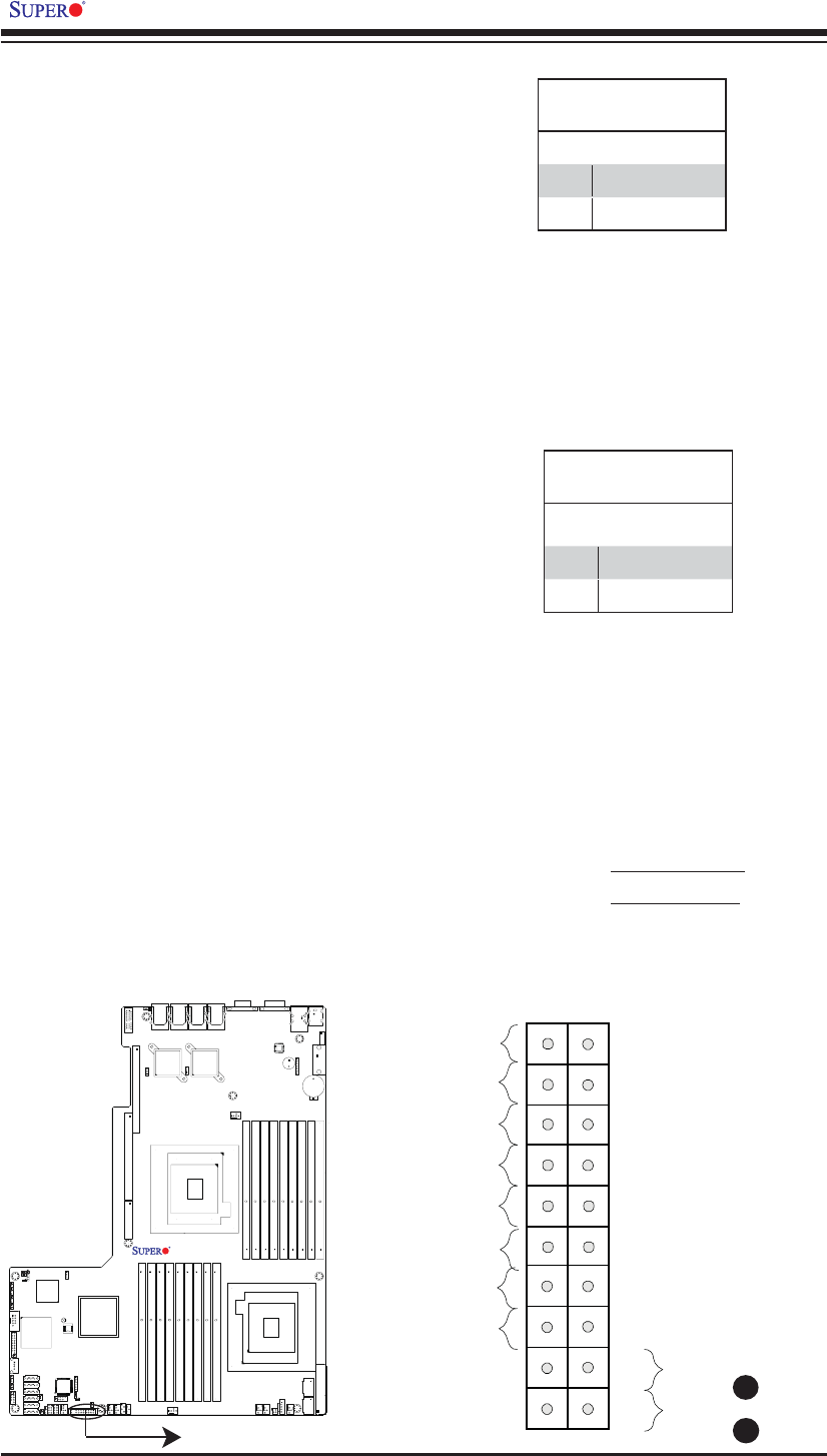
The Power Button connection is located
on pins 1 and 2 of JF1. Momentarily
contacting both pins will power on/off
the system. This button can also be con-
fi gured to function as a suspend button
(with a setting in the BIOS - see Chapter
5). To turn off the power when the system
is in suspend mode, press the button for
at least 4 seconds. Refer to the table on
the right for pin defi nitions.
Power Button
Pin Defi nitions (JF1)
Pin# Defi nition
1 PWR Button
2 Ground
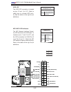
Reset Button
The Reset Button connection is located
on pins 3 and 4 of JF1. Attach it to a
hardware reset switch on the computer
case. Refer to the table on the right for
pin defi nitions.
Reset Button
Pin Defi nitions (JF1)
Pin# Defi nition
3 Reset
4 Ground
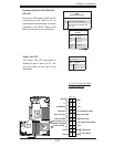
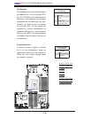
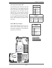
A. Reset Button
B. PWR Button
A
B
X8DTU-LN4F+
Rev. 2.0