


Chapter 3: Installation
3-31
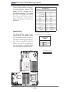
SP1
JF1
JD1
JWF1
JIPMB2
IPMB1
JP8
VGA2
JPK1
JPW1
JBT1
JPW3
JPW2
J3
J2
J1
JPL2
JPG1
JWD
FAN4
FAN5
FAN3
FAN2
FAN1
FAN6
JBT1
D20
LE11
JL1
JI2C1
JI2C2
JPI2C
USB7
USB4/5
USB2/3
Clear
COMS
JTPM
COM2
UIOP
UID
LAN4
LAN3
LAN2
LAN1
VGA1
COM1
FAN8/CPU1
FAN7/CPU2
CPU2
P1-DIMM2C
P1-DIMM1C
P1-DIMM3C
JTAG of CPLD
SXB1: PCI-E 2.0 x16
SXB3: PCI-E 2.0 x8
SXB2: PCI-E 2.0 x8+x4
P1-DIMM3B
P1-DIMM3A
P1-DIMM1A
P1-DIMM1B
P1-DIMM2B
P1-DIMM2A
CPU1
USB0/1
IPMI_LAN
P2-DIMM2C
P2-DIMM1C
P2-DIMM3C
P2-DIMM3B
P2-DIMM3A
P2-DIMM1A
P2-DIMM1B
P2-DIMM2B
P2-DIMM2A
JPL1
KB/MS
BIOS
FPCTRL
LE1
SATA0~5
LAN1
LAN2
IOH-36D
ICH10R
Intel
Intel
BMC
Winbond
PHY
USB6
T-SGPIO2
T-SGPIO1
X8DTU-LN4F+
JOH1
WOR1
Rev. 2.0
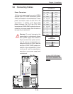
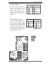
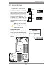
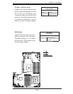
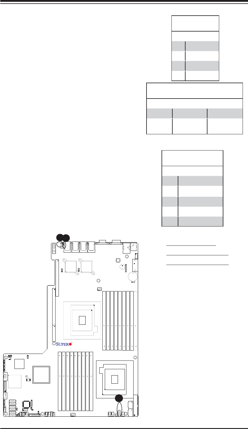
Power SMB (I
2
C) Connector
Power System Management Bus (I
2
C) Con-
nector (JPI
2
C) monitors power supply, fan
and system temperatures. See the table on
the right for pin defi nitions.
PWR SMB
Pin Defi nitions
Pin# Defi nition
1 Clock
2 Data
3 PWR Fail
4 Ground
5 +3.3V
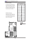
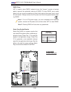
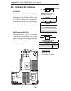
A
B
A. Rear UID Switch
B. Rear UID LED (LE11)
C. PWR SMB Connector
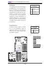
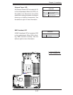
Unit Identifi cation Switch/LED
A Unit Identifi er switch (UID) and a rear UID
LED indicator (LE11) are located next to LAN
ports on the back of the chassis. When the
user pushes the rear UID switch, the rear
UID LED (LE11) will be turned on. Push the
UID switch again to turn off the LED indica-
tor. The UID switch provides easy identifi ca-
tion of a system unit that may be in need of
service. See the tables on the right for more
information.
UID Switch (UID)
Pin Defi nitions
Pin# Defi nition
1 Ground
2 Ground
3 Button In
4 Ground
C
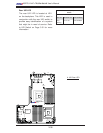
UID LED (LE11)
Status
Color/State OS Status
Blue: On Windows OS Unit Identifi ed
Blue:
Blinking
Linux OS Unit Identifi ed