


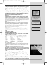
LNCs are supplied with power by means of the coaxial cable,
to achieve this the receiver supples either 14 or 18 volt power
Interim frequency:
The frequency range broadcast by the satellite cannot be
transmitted via a cable. Therefore the LNC converts the sig-
nal to the interim frequency range of 950 to 2150 MHz. This
makes it possible for the digital receiver to receive and pro-
cess the signal.
1. IF = Interim frequency
11 Technical data
DBS tuner:
Input frequency range 950 .... 2150 MHz
Input level range - 65 dBm ... - 25 dBm
DBS tuner input F - connector
Input/output impedance 75 Ohms
Output for 1. IF 950 ... 2150 MHz (loop through)
AFC capture range +/- 3 MHz
Demodulation Shaped QPSK
Symbol rate 1 ... 45 Mbaud/s, SCPC/ MCPC
FEC Viterbi and Reed-Solomon
Viterbi rates 1/2, 2/3, 3/4, 5/6, 7/8, automatic
adaptation
Roll-off Factor 35 %
Demultiplexing: according to ISO 13818-1
Common Interface:
Type 1 Common Interface slot for CI
module
Power requirement max. 0,3A/5V
PLL modulator: UHF, Channel 21 ... 69
Antenna input 47 ... 862 MHz
Antenna output 47 ... 862 MHz
Video decoding:
Video compression MPEG-2 and MPEG-1 compatible
Up to MP@ML (main profile @
main level)
Video standard PAL / 25 Hz
Active image 720 Pixel x 576 lines
Picture format 4 : 3 / 16 : 9
Picture material 16:9 Automatic adaptation for 16:9 TV
sets (via SCART)
Letterbox filtering for 4:3 TV sets
Audio decoding:
Audio compression MPEG-1 & MPEG-2 Layer I and II
Audio Mode Dual (main/sub), Stereo
Sampling frequencies 32 kHz, 44.1 kHz, 48 kHz
Audio parameters:
Output analogue:
Output level L/R 0,5 V r.m.s. (nominal)
65
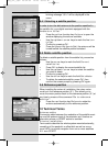
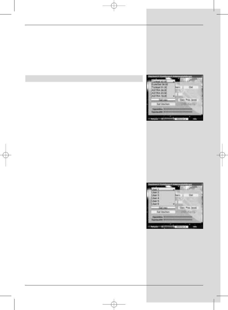
(Fig. 9-11)
(Fig. 9-10)
Bed_anl_.qxd 20.02.04 16:29 Seite 65