


Telenetics 2185
2-3
INSTALLATION PROCEDURE
Equipment Assembly
The 2185 is shipped as a completely assembled unit with the printed cir-
cuit board and power supply sub-assemblies already installed.No further
assembly is required.
Installation Tools Required
The only tool required is a small slot screwdriver to tighten the screws
securing the interface cable connectors to the connectors on the unit's
rear panel.
Mechanical Installation
The 2185 is a “tabletop” unit.No provisions are made for securing the
unit to any surface.
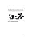
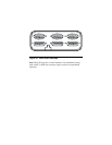
Cabling
All external connections to the 2185 are made via EIA 232-D, 25-pin,
connectors located on the rear panel (see Figure 2-1) and their associ-
ated straight-through cables.There are six connectors, one for the main
channel, and one for each subchannel.
In Figure 2-1:
Port 0 = Main Channel Port 1 = Subchannel 1
Port 2 = Subchannel 2 Port 3 = Subchannel 3
Port 0 = Subchannel 4 Port 1 = Subchannel 5