


Telenetics 2185
3-5
In certain synchronous configurations, the internal clock generator is
not used and the data rate is determined by the selected external clock
source. (For details, refer to the section on function switch segments 2-5
and 2-6 - Clock Routing.) The internal clock generator is also used in
asynchronous applications when Data Contention is selected.
Switch Segment 2-1 — Contention Mode
• Switch 2-1 set to up position – Control Signal Contention
• Switch 2-1 set to down position – Data Contention
In applications where the subchannel devices toggle control signals, set
this switch to the up position for Control Signal Contention. Where
active control signals are not provided, set to the down position for Data
Contention. This selects the RTS or DCD control signal for contention,
depending on whether the subchannel is configured as a DTE or DCE.
When Data Contention mode is selected, switch segments 2-7 and/or 2-
8 must be strapped ON.
Switch Segment 2-2 — Data Format
• Switch 2-2 set to up position – Synchronous format
• Switch 2-2 set to down position – Asynchronous format
Set this switch to the up position for Bisynchronous or HDLC applica-
tions (synchronous operation). When set to the down position, (asyn-
chronous operation selected), the retiming buffer is bypassed.
Switch Segment 2-3 — Synchronous Data Retiming Buffer
• Switch 2-3 set to up position – Normal
• Switch 2-3 set to down position – Buffer bypassed
When the 2185 is configured for asynchronous data format (function
switch 2-2 is set to the down position), that switch may be ignored.
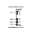
2-7 Up
Down
Sets main channel RTS or DCD transparent
Straps main channel RTS or DCD ON
2-8 Up
Down
Straps main channel inbound CTS ON
Sets main channel inbound CTS transparent
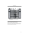
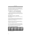
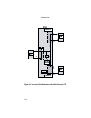
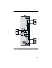
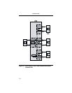
Table 3-3. Function Switch Two Summary
Function
Switch
Switch
Position Function