


Telenetics 2185
3-3
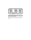
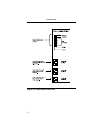
FUNCTION SWITCHES
The front-panel-mounted controls consist of three Dual In-line Package
(DIP) function switches. Switch banks one and two contain eight indi-
vidual switches and switch three contains six individual switches.
The role of function switches one, two and three is summarized in
Tables 3-1 through 3-5. The following paragraphs describe these func-
tions in more detail.
Function Switch One
Function switch one is an eight-segment DIP switch used to enable or
disable each of the five subchannels. It is also used to set the clock data
rate.
Switch segments 1-1 through 1-5 Disable/Enable subchannels one
through five respectively. Their operation is described as follows:
• Switch 1-n is set to up position to disable Subchannel n
• Switch 1-n is set to the down position to enable Subchannel n,
where n = 1 - 5
Subchannels may be disabled to prevent them from contending for the
main channel. The main channel broadcasts to all subchannels, whether
the subchannels are enabled or disabled. Unused subchannels should be
disabled (i. e., appropriate switch set to the up position).
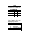
Table 3-1. Enabling/Disabling Subchannels
Switch Up Down
1-1 Disable Subchannel 1 Enable Subchannel 1
1-2 Disable Subchannel 2 Enable Subchannel 2
1-3 Disable Subchannel 3 Enable Subchannel 3
1-4 Disable Subchannel 4 Enable Subchannel 4
1-5 Disable Subchannel 5 Enable Subchannel 5