


Telenetics 2185
3-6
With synchronous data transmission, the data retiming buffer must be
used except when all subchannels are connected to DTE devices. The
data retiming buffer may then be bypassed to permit passing Bisynchro-
nous multiple messages in Data Contention mode.
Switch Segment 2-4 — Anti-Streaming Enable/Disable
• Switch 2-4 set to up position – Anti-Streaming Disabled
• Switch 2-4 set to down position – Anti-Streaming Enabled
Enabling Anti-Streaming limits a subchannel message to 25 seconds. If
subchannel messages are greater than 23 seconds in length, anti-stream-
ing should be disabled.
Switch Segment 2-5 and 2-6 — Clock Routing
When the 2185 is configured for asynchronous data format switches 2-5
and 2-6 are ignored.
If the 2185 is configured for synchronous data format, switches 2-5 and
2-6 are used to select the master clock source. The network may be
clocked from the main channel device, the 2185's internal clock, or the
Subchannel 1 device if it is a DCE device.
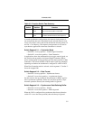
Switch segments 2-5 and 2-6 much be set as described in Table 3-4.
Note that only the configurations listed in Table 3-2 are valid; all other
combinations are illegal and result in errors.
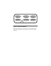
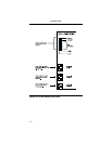
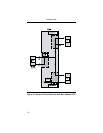
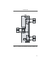
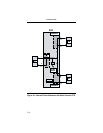
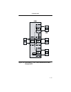
When the 2185 is configured for subchannel 1 DCE clock timing (Fig-
ures 3-7 and 3-8), the 2185 uses the Receive Clock signal of the DCE
for timing. Should DCE's clock signal fail, the Clock Alarm on the 2185
illuminates and the 2185 reverts to its own internal oscillator.
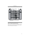
Note: X = does not matter
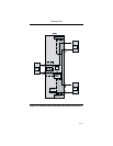
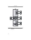
Table 3-4. Clock Routing Configurations
Fig Ref.
Clock
Source Subchannel 1 Set 2-5 to Set 2-6 to
3-3/4 Main Channel X Up Down
3-5/6 Internal X Down Down
3-7/8 Sub Ch. 1 DCE Down Up