


EVM Basic Functions
1-3
EVM Overview
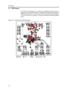
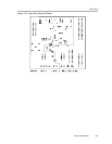
The REF102 precision reference derives its power of ±15-V supply through
J10 or J7 terminal. The (plus) 15 V connects through J10-1 or J7-2 terminals,
while the (minus) -15 V connects through J10-3 or J7-4 terminals. They are
both referenced to analog ground through J10-2 and J7-1.
The DAC7741 has a REFEN
pin to enable the internal reference circuit or
disable it and select an external reference source. The REFEN
pin can be
hardware driven through W2 jumper. Likewise, it can also be software driven
through J2-11 terminal via W2 jumper by shorting pins 1 and 2. The REF
OUT
pin of the DAC7741 must be connected to the REF
IN
pin to use the internal
voltage reference. This can be done through W3 jumper by shorting pins 1 and
2. Shorting pins 2 and 3 of W3 selects the external voltage reference source.
The on-chip reference buffer output is channeled out through V
REF
pin which
is used to set up the DAC7741 output amplifier into one of three voltage output
modes. V
REF
can also be used to drive other system components that require
external voltage reference.
When applying an external voltage reference through TP1 or J4-20,
make sure that it does not exceed 10 V maximum. Otherwise, this
can permanently damage the DAC7741, U11, device under test.
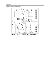
1.3 EVM Basic Functions
The DAC7741 EVM is a functional evaluation platform to test certain functional
characteristics of the DAC7741 digital-to-analog converter. Functional
evaluation of the DAC device can be accomplished with the use of any
microprocessor, TMS320VC33 DSP, or some sort of a waveform generator.
The headers, J1, J2 and J3 are provided to channel in the necessary control
signals and data needed to interface a microprocessor/microcontroller, TI’s
DSP starter kit or waveform generator to the DAC7741 EVM, through a custom
cable.
A specific adapter interface card is also available for most of TI’s DSP starter
kit (DSK) and the card model depend on the type of the DSP starter kit to be
used. The user must specify the DSP used as an interface to acquire the right
adapter interface card. Call or email TI for more information regarding the
adapter interface card.
The output of the DAC can be monitored through two different access points
which are as follows; a BNC connector (J5, if installed), and also a header
through pin 2 of J4. The 6-pin header, W13, provides different options of the
DAC output, but requires the output op-amp, U2, to be configured correctly first
for the desired waveform characteristic. Shorting pins 1 and 2 of W13 allows
the user to monitor the raw output of the DAC7741.