


EVM Basic Functions
1-4
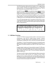
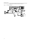
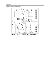
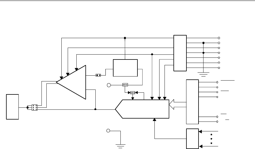
A block diagram of the EVM is shown below in the Figure 1-1.
Figure 1-1. EVM Block Diagram
DAC Out
(J4)
(J5)
W13
Output
Buffer
Module
W14
W4
W3
External
Reference
Module
(J2)
(J3)
(J6)
(J7)
+15 V
-15 V
TP1
+REF
IN
Ext Ref
Input
REF
IN
REF
out
DAC Module
TP2
(J1)
VCC
VDD
VSS
+15 V
GND
-15 V
GND
VCC
VDD
VSS
REFEN
LDAC
RST
RSTSEL
CS
R/W
DB15 (MSB)
DB1 (LSB)