


Jumper Setting
3-5
EVM Operation
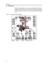
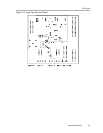
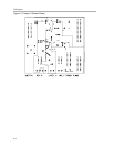
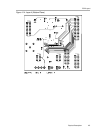
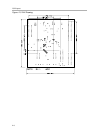
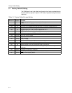
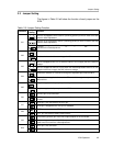
3.3 Jumper Setting
The figures in Table 3-5 will show the function of each jumper on the
EVM.
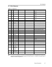
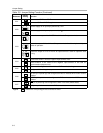
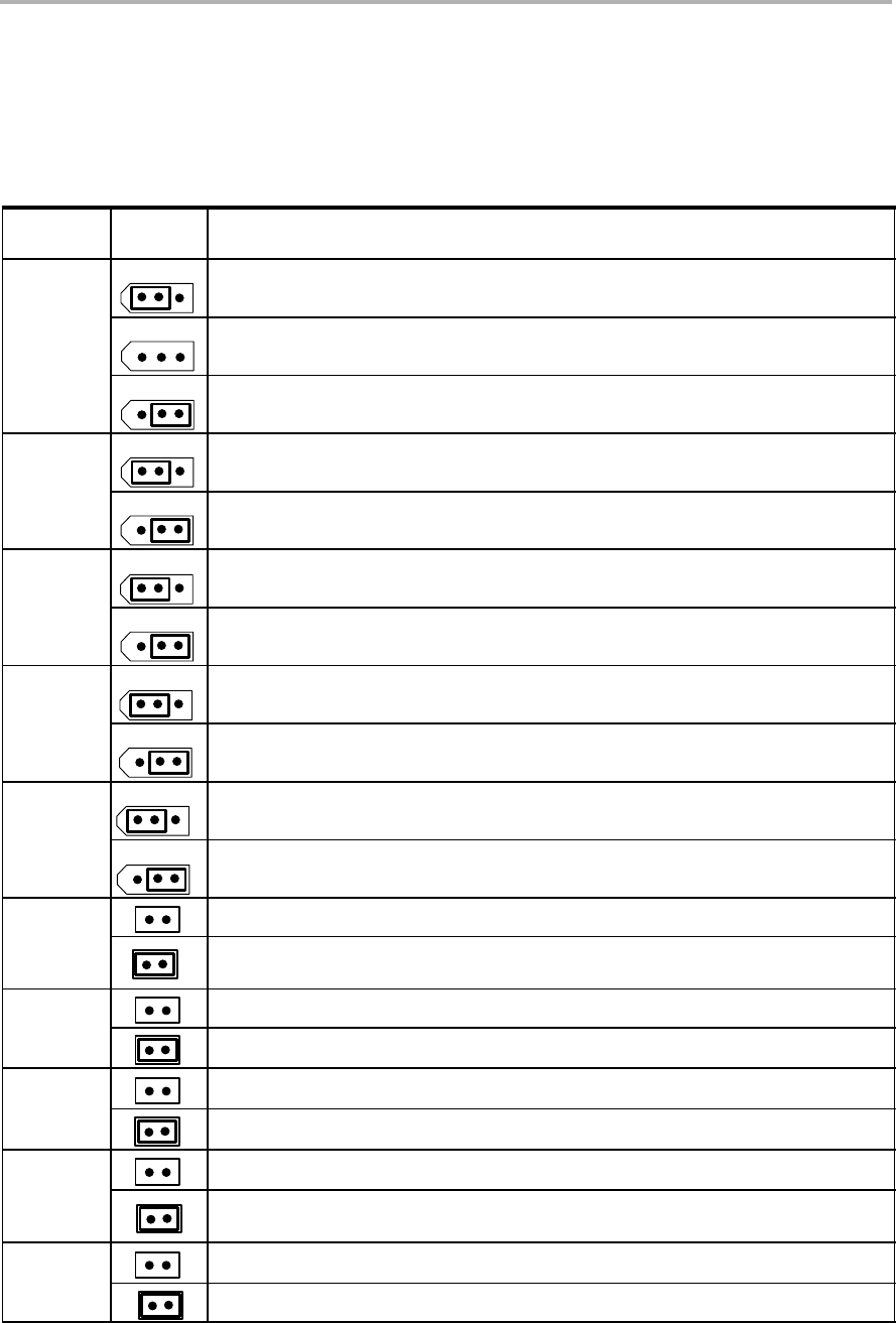
Table 3-5.Jumper Setting Function
Reference
Jumper
Setting
Function
13
R
OFFSET
is strapped to V
REF
to set V
SJ
(summing junction) to V
REF
/2. Refer to the data
sheet for offset adjustment.
W1
13
R
OFFSET
is not connected to set V
SJ
(summing junction) to V
REF
/3. Refer to the data
sheet for offset adjustment.
13
R
OFFSET
is strapped to AGND to set V
SJ
(summing junction) to V
REF
/6. Refer to the
data sheet for osset adjustment.
13
Disables the internal reference voltage.
W2
13
Enables the internal reference voltage of +10V.
1
3
REF
IN
is strapped to REF
OUT
to allow the internal 10 V to supply the DAC reference
voltage.
W3
13
REF
IN
is strapped to exREFin to allow either the onboard adjustable reference or user
supplied reference to supply the DAC reference voltage.
13
Routes the onboard 10 V reference through the adjustable pot to W3 and W14.
W4
13
Routes the user supplied reference from TP1 or J4-20 through the adjustable pot to
W3 and W14.
13
Negative supply rail of op-amp is powered by -15 V.
W5
13
Negative supply rail of op-amp is tied to AGND.
REFADJ pin is not connected.
W6
REFADJ pin is connected to R1 pot for gain adjustment input when internal reference
is used.
RFB2 pin is not connected to the V
OUT
pin.
W7
RFB2 pin is strapped to the V
OUT
pin for feedback.
TEST pin not connected to DGND.
W8
TEST pin connected to DGND (default mode).
SJ (summing junction) pin of the DAC output amplifier is not connected.
W9
SJ (summing junction) pin of the DAC output amplifier is connected to R2 pot to allow
small amount of current for offset adjustment.
RFB1 pin is not connected.
W10
RFB1 pin is strapped to RFB2 pin for DAC V
OUT
feedback.