


Host Processor Operation
3-3
EVM Operation
3.2 Host Processor Operation
The host processor basically drives the DAC, so the DACs proper operation
depends on the successful configuration between the host processor and the
EVM board. In addition, a properly written code is also required to operate the
DAC.
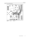
A custom cable can be made specific to the host interface platform. The EVM
allows interface to the host processor through J2 and J3 header connectors
for the control signals, and J1 header connector for the data input. The output
can be monitored through the J5 BNC connector (if installed) or J4 header
connector. An interface adapter card is also available for specific DSP starter
kits as mentioned in Chapter 1 of this manual.
The EVM includes an optional signal conditioning circuit for the DAC output
through an external operational amplifier, U2. This is set to a unity gain
configuration by default. Regardless, the raw output of the DAC can be probed
through W13 pin 2 so that it can be compared with the output of U2 if
necessary. The output terminals J5 and J4 are provided to monitor the desired
output of the DAC by shorting the respective pins of W13.
The following sections describe the different configurations of the output
amplifier, U2.
3.2.1 Unity Gain Output
The buffered output configuration is used to prevent loading the DAC7741 and
should closely match the raw output of the DAC with maybe some slight
distortion because of the feedback resistor and capacitor. The user can tailor
the feedback circuit to closely match their desired wave shape by simply
desoldering R7 and C11 and replacing them with the desired values. You can
also simply get rid of R7 and C11 altogether and just solder a zero-Ω resistor
in replacement of R7, if desired.
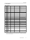
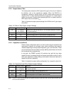
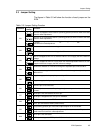
Table 3-2 shows the jumper setting for the unity gain configuration of the DAC
external output buffer in unipolar or bipolar mode.
Table 3-2.Unity Gain Output Jumper Settings
Jumper Setting
Reference
Unipolar Bipolar
Function
W5 2-3 1-2 Supplies the voltage for the negative rail of op-amp.
W12 2-3 1-2 Supplies the voltage for the positive rail of op-amp.
W13 3-4 3-4 DAC output is channeled to the output terminals.
W14 Open Open exREFin is disconnected from the negative input of op-amp.
W15 Open Open Disconnect negative input of op-amp from GND