


Jumper Setting
3-6
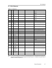
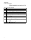
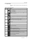
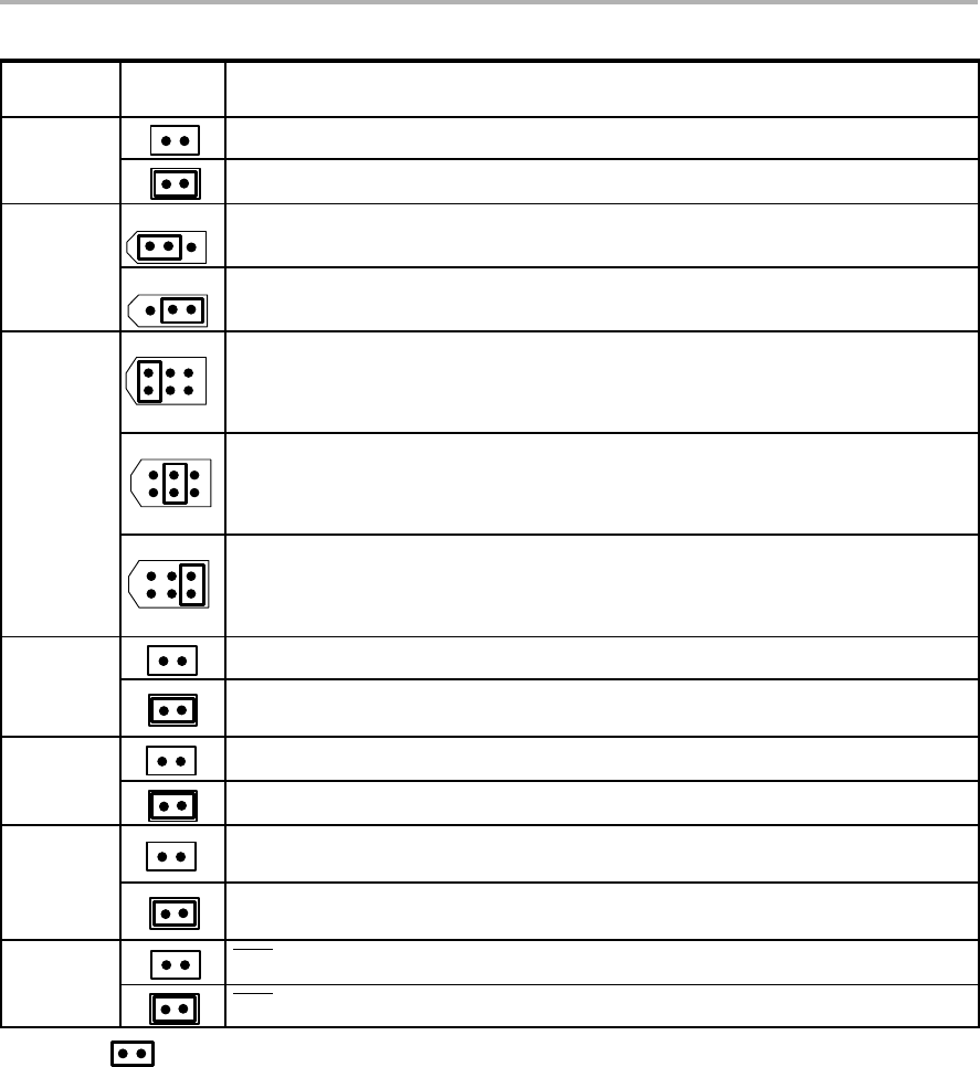
Table 3-5. Jumper Setting Function (Continued)
Reference
Jumper
Setting
Function
Disconnects AGND from DGND.
W11
Connects AGND and DGND together.
13
Positive supply rail of op-amp is powered by +15V.
W12
13
Positive supply rail of op-amp is powered by V
CC
.
264
153
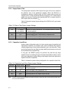
Routes the raw output of the DAC7741 to J4-2 and J5 output terminals.
W13
264
153
Routes the output of U2 to J4-2 and J5 output terminals. Used for unipolar and bipolar
modes of operation.
264
153
Routes the output of U2 to J4-2 and J5 output terminals. Used for capacitive load
driving.
Disconnects exREFin from the negative input terminal of U2.
W14
Allows exREFin to be routed to the negative input terminal of U2 used for
experimentation purposes only.
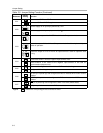
Disconnect the negative terminal of U2 to AGND and disable 2x gain.
W15
Configures U2 for a 2× gain output.
RSTSEL pin is pulled high and configures the DAC to midscale when POR or reset is
initiated.
W16
RSTSEL pin is pulled low and configures the DAC to minscale when POR or reset is
initiated.
RST pin is pulled high and configures the DAC not to reset (default state).
W17
RST pin is pulled low and holds the DAC to reset state.
Legend: Indicates the corresponding pins that are shorted or closed.