


Host Processor Operation
3-4
3.2.2 Output Gain of Two
This configuration allows the DAC output with a gain of two, but is limited to
the effective rails of the operational amplifier. When the DAC7741 is
configured to operate in bipolar mode, the DAC output must be within the
range of 12 V
P- P
or less. Anywhere above the range of 12 V
P- P
would clip the
output of the op-amp. Likewise, when operating the DAC in unipolar mode, the
DAC output must not exceed 6 V
P- P
.
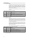
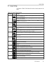
Table 3-3 shows the proper jumper settings of the EVM for the 2× gain output
of the DAC.
Table 3-3.Gain of Two Output Jumper Settings
Reference Jumper Setting Function
W5 1-2 (Bipolar)
2-3 (Unipolar)
Negative rail of the op-amp tied to -15 V for bipolar operation or AGND
for unipolar operation.
W12 1-2 Positive rail supply of the op-amp tied to 15 V
W13 3-4 Amplified output of DAC is channeled to the output terminals
W14 Open Disconnect exREFin from negative input of op-amp
W15 Close Configures op-amp for a 2× gain output
3.2.3 Capacitive Load Drive
Another output configuration option is to drive a wide range of capacitive load
requirement. However, all op-amps under certain conditions may become
unstable depending on the op-amp configuration, gain, and load value. These
are just few factors that can affect op-amps stability performance and should
be considered when implementing.
In unity gain, the OPA627 op-amp, U2, performs very well with very large
capacitive loads. Increasing the gain enhances the amplifier’s ability to drive
even more capacitance, and by adding a load resistor would even improve the
capacitive load drive capability.
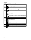
Table 3-4 shows the jumper setting configuration for a capacitive load drive.
Table 3-4.Capacitive Load Drive Output Jumper Settings
Reference Jumper Setting Function
W5 1-2 (Bipolar)
2-3 (Unipolar)
Negative rail of the op-amp tied to -15 V for bipolar operation or AGND
for unipolar operation.
W12 1-2 Positive rail supply of the op-amp tied to 15 V
W13 5-6 Capacitive load drive output of DAC is channeled to the output terminals
W14 Open Disconnect exREFin from negative input of op-amp
W15 Open Disconnect R12 (see note)
Note: If there is a need to incrementally adjust the capacitive load output, replace R12 with a capacitor with the desired capaci-
tance value and CLOSE W15.