


Factory Default Setting
3-2
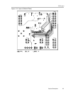
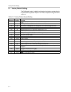
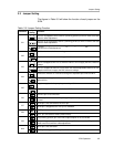
3.1 Factory Default Setting
The EVM board is set to its default configuration from factory as described on
the table below to operate in bipolar ±10V mode of operation using the internal
reference.
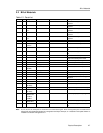
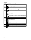
Table 3-1.Factory Default Jumper Setting
Reference
Jumper
Position
Function
W1 OPEN V
REF
output pin is floated and not used for offset adjustment.
W2 2-3 REFEN pin is tied to AGND to enable 10 V internal reference.
W3 1-2 REF
OUT
pin is strapped to REF
IN
to provide 10 V internal voltage reference.
W4 OPEN Onboard external reference through U3 is disconnected.
W5 1-2 Negative supply rail of U2 op-amp is supplied with -15 V.
W6 OPEN REFADJ pin is floated.
W7 CLOSE RFB2 pin is strapped to V
OUT
pin for DAC output feedback.
W8 CLOSE TEST pin is tied to DGND.
W9 OPEN SJ pin is floated.
W10 OPEN RFB1 is floated.
W11 CLOSE AGND and DGND are tied together to a common point.
W12 1-2 Positive supply rail of U2 op-amp is supplied with 15 V.
W13 3-4 Buffered output of DAC is channeled through to J5 and J4-2.
W14 OPEN External reference is disconnected from the negative input of U2 to configure U2 for
unity gain.
W15 OPEN Configure U2 op-amp for unity gain.
W16 OPEN RSTSEL pin is tied high to set DAC reset value to midscale.
W17 OPEN RST pin is tied high by default.