


Bill of Materials
2-7
Physical Description
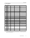
2.2 Bill of Materials
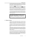
Table 2-1.Parts List
Item # Qty Designator Manufacturer Part Number Description
1 1 C8 Panasonic ECJ3VB1C105K 1 µF, 1206 multilayer ceramic
capacitor
2 2 C9 C10 Panasonic ECUV1H103KBM 0.01 µF, 1206 multilayer ceramic
capacitor
3 5 C1 C2 C3 C7
C13
Panasonic ECJ3VB1C104K 0.1 µF, 1206 multilayer ceramic
capacitor
4 1 C12 Panasonic ECUV1H102JCH 1 nF, 1206 multilayer ceramic
capacitor
5 5 C4 C5 C6 C11
C14
Kemet C1210C106K8PAC 10 µF, 1210 multilayer ceramic X5R
capacitor
6 1 R8 Panasonic ERJ-8GEY0R00V 0 Ω, 1/4W 1206 chip resistor
7 2 R7 R10 Panasonic ERJ-8ENF2002V 20 kΩ, 1/4W 1206 chip resistor
8 6 R4 R5 R6 R12
R13 R14
Panasonic ERJ-8ENF1002V 10 kΩ, 1/4W 1206 chip resistor
9 2 R1 R2 Bourns 3214W-103E 10 kΩ, BOURNS_32X4W Series 5T
pot
10 1 R11 Bourns 3214W-104E 100 kΩ, BOURNS_32X4W Series 5T
pot
11 1 R3 Panasonic ERJ-8ENF1003V 100 kΩ, 1/4W 1206 chip resistor
12 2 J6 J7 Samtec IPT1-105-01-S-D-VS 5X2X0.1
10-pin 3A isolated power socket
13 3 J2 J3 J4 Samtec TSM-110-01-S-DV-M 10X2X.1, 20-pin 0.025” sq SMT socket
14 1 J1 Samtec TSM-116-01-S-DV-M 16X2X.1, 32-pin 0.025” sq SMT socket
15 2 J11 J12 Lumberg KRMZ2 2-pin Terminal screw connector
16 1 J5 (Not
Installed)
AMP (TYCO) 227699-2 PCB Mounted BNC - Amphenol
17 1 J10 Lumberg KRMZ4 4-pin Terminal screw connector
18 1 U1 Texas Instruments DAC7741 16-bit, 48-LQFP DAC
19 1 U2 Texas Instruments OPA627AU 8-SOP(D) Precision op amp
20 1 U3 Texas Instruments REF102AU 10 V, 8-SOP(D) Precision voltage
reference
21 2 TP1 TP2 Cambion 180-7337-02-05 Turret terminal test point
22 1 W13 Samtec TSW-103-07-L-D 3X2X 0.1 6-Pin IDC header
23 3 P2 P3 P4
(see Note)
Samtec SSW-110-22-S-D-VS-P 20-pin 0.025” sq SMT terminal strips
24 1 P1 (see Note) Samtec SSW-116-22-S-D-VS-P 32-pin 0.025” sq SMT Terminal Strips
25 2 P6 P7
(see Note)
Samtec IPS1-105-01-S-D-VS 3A Isolated power header
26 10 W6 W7 W8
W9 W10 W11
W14 W15
W16 W17
Samtec TSW-102-07-L-S 2 Position jumper_ 0.1” spacing
27 6 W1 W2 W3
W4 W5 W12
Samtec TSW-103-07-L-S 3 Position Jumper_ 0.1” spacing
28 1 R9 Bourns 3214W-203E 20 kΩ, BOURNS_32X4W Series 5T
pot
Note: P1, P2, P3, P4, P8, & P9 parts are not shown in the schematic diagram. All the P designated parts are installed in the
bottom side of the PC Board opposite the J designated counterpart. Example, J1 is installed on the topside while P1 is
installed in the bottom side opposite of J1.