


Step 1: Installing the EVM Board in Your PC
4
2. Step 1: Installing the EVM Board in Your PC
This section contains the hardware installation information for the EVM.
Preparing the EVM board for installation
Before you install the EVM board, you must be sure that the board’s switches
are set to correctly identify the I/O space that the board can use. The ’C3x EVM
board has four switches:
- Switches 1 and 2 identify your system’s I/O address space. You can
change these switch settings to identify the I/O address space that the
EVM uses in your system.
- Switches 3 and 4 are for manufacturing test. Leave these switches in the
default positions.
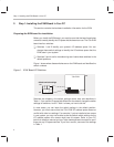
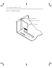
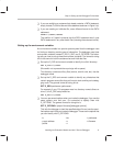
Figure 1 shows where these switches are on the EVM board and identifies the
switch numbers.
Figure 1. EVM Board I/O Switches
123 4
on
off
’C3x EVM
default switch settings
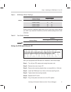
Switches are shipped in the default settings shown here and described in
Table 1. If you use an I/O space that differs from the default, change the switch
settings for switches 1 and 2. Table 1 shows you how to do this.
In most cases, you can leave the switch settings in the default position.
However, you must ensure that the ’C3x EVM I/O address space does not
conflict with other bus settings. For example, if you’ve installed a bus mouse
in your system, you may not be able to use the default switch settings for the
I/O address space—the mouse might use this space. Refer to your PC
technical reference manual and your other hardware-board manuals to see if
there are any I/O space conflicts. If you find a conflict, use one of the settings
in Table 1.