


TOSHIBA
23
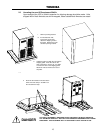
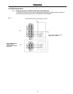
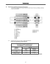
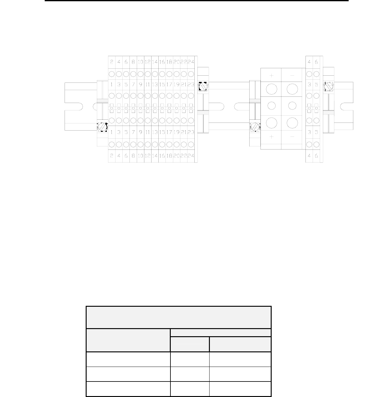
4.2 Control Circuit and External Battery Interface Connections 15/25/30/33 kVA
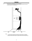
The following illustrates the wiring connections of the Control Circuits, and Battery Interface
Circuits.
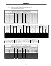
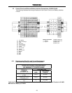
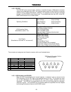
4.2.1 Recommended Wire Size and Torque Requirements
UPS Control and Battery Interface 15/25/30/33kVA
Minimum Wire Size and Torque Requirements
UPS Control and Battery Interface Circuits
USE MINIMUM 75° C COPPER WIRING
15/25/30/33 kVA
TERMINAL
(TERMINAL #)
AWG
TIGHTENING
TORQUE
UPS CONTROL CIRCUITS
(1-24)*
14-16 8 in-lbs.
BATTERY CONTROL
CIRCUITS (3-6)*
14-16 8 in-lbs.
BATTERY
(+/-)
4 51 in-lbs.
*Indicates Class 1 wiring methods is to be used. Maximum Wire Size for Control Circuits is 12 AWG.
Maximum for Battery is 2 AWG.
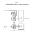
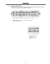
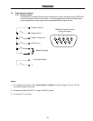
(1) Low Battery
(2) Battery Discharge
(3) Fault
(4) Not Used
(5) Inverter Supply
(6) Inverter Supply
(7) P24A3
(8) Remote Run
(9) P24A3
(10) Remote Stop
(11) Bypass
(12) GND
(13) EPO
(14) EPO
Battery Connection
(+) Positive
(-) Negative
(3) Battery Shunt Trip
(4) Battery Shunt Trip
(5) Battery Aux.
(
6
)
Batter
y
Aux.