


TOSHIBA
40
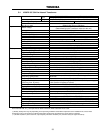
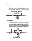
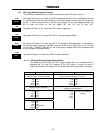
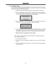
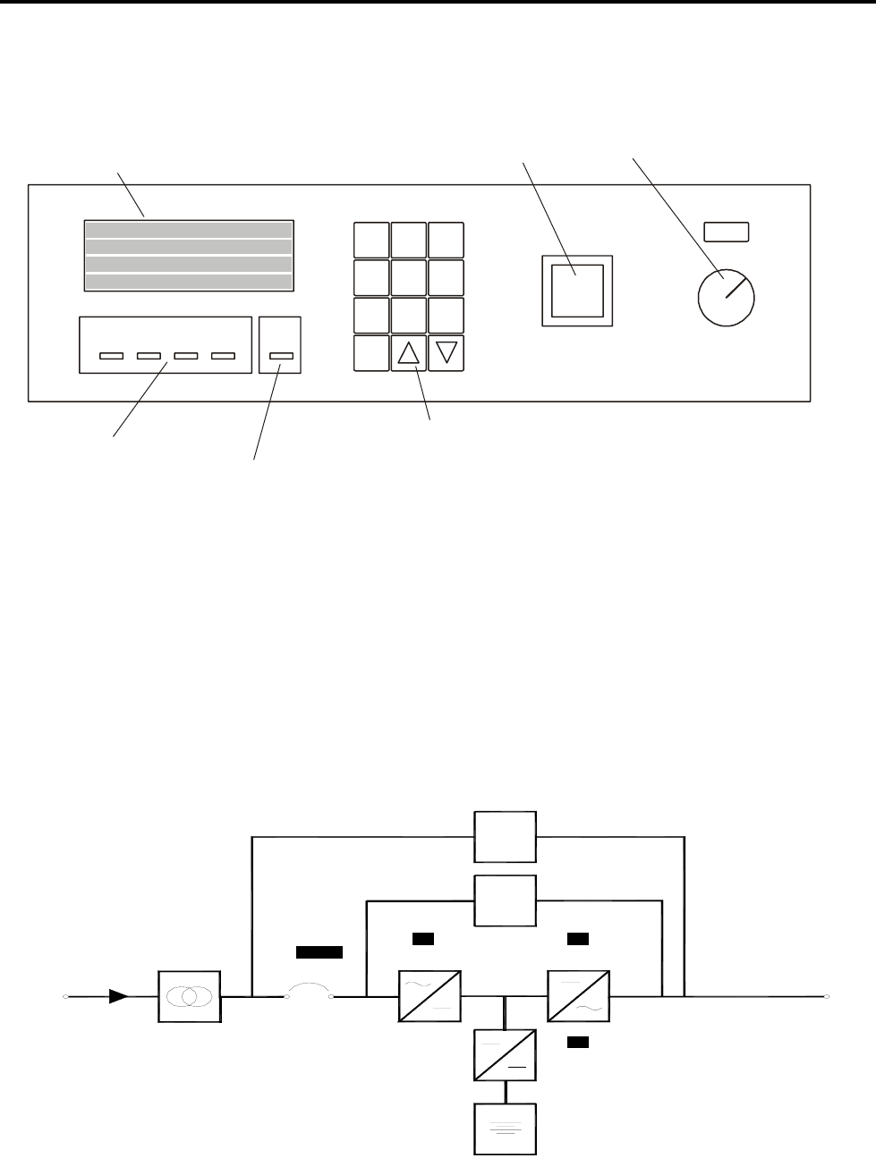
5.11 Front Panel Layout (All Units)
Refer to the following illustration for the entire UPS front panel operating procedures.
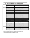
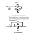
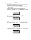
5.12 EPO (Emergency Power Off) Function
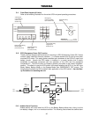
These units are equipped with terminals for receiving an EPO (Emergency Power Off) "closed
contact" switch command from two locations: (1) a remote location and (2) from a front panel
mounted EPO switch. This safety feature enables quick shutdown of the UPS AC output and
battery circuits. Usually the EPO switch is installed in a central location that is easily
accessible to personnel concerned with the operation of the UPS and the equipment
connected to it. The EPO function is initiated by pressing the switch to the closed "shutdown"
position. The effect of using the EPO switch is the same whether the UPS is in the AC Input
Mode, Battery Backup Mode, or the Bypass Mode. See 'EMERGENCY OFF' screen. The
following figure shows the UPS condition after application of the EPO switch. Use the Start-
up Procedure for restarting the unit.
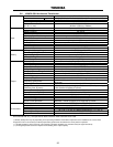
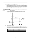
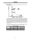
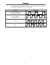
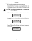
5.13 Audible Alarm Functions
Audible alarms will sound when the UPS is in the Battery Backup Mode, has a fault, is at the
low battery voltage, or is in an overload condition. The following chart shows the audible alarm
Input
Power
MCCB
Input
Transformer
Model
Converter Inverter
Chopper
Batteries
Output
Power
Bypass
MBS
TRIPPED
OFF OFF
OFF
line-1
line-2
line-3
line-4
INVAC IN
BYP
BATT
FAULT
MONI
BATT F1
IN OUT
BATT
TEST
BUZZ
STOP
MENU ENTER
RESET
EPO
STOP RUN
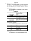
UPS
4200 Series
ON-LINE
UNINTERRUPTIBLE POWER SYSTEM
4-line liquid
crystal display
screen (see
Section 6.9)
Emergency
power off switch
(see Section 6.6)
STOP/RUN key
switch
Green light emitting
diodes (LED)
(see Section 6.8)
Red light emitting
diode (LED)
(see Section 6.8)
12-key Data entry
keypad (see
Section 6.14)