


TOSHIBA
29
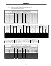
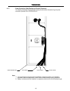
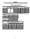
4.5.2 RS-232C
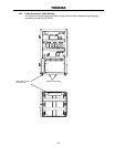
The RS-232C serial communication interface is available through a DB9 female connector
located on the backside of the UPS. This interface allows control of the UPS from a computer
network running Toshiba RemotEyeII™ software. The computer and the UPS are connected
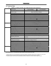
through a serial RS-232C communication port. The available data from the UPS, via the RS-
232C communication link, is shown below:
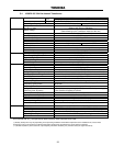
Input Voltage Output Voltage
Input Frequency Output Frequency
Battery Voltage Output Current
Operating Conditions
UPS Operating Status
(Described as “yes or “no”)
Utility Power OK
Low Battery Voltage Detected
UPS in BYPASS Mode
UPS in NORMAL Mode
Input and Output Frequency Synchronized
UPS FAULT Occurred
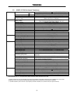
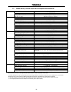
Fault Details
(Described as “occurred” or “not occurred”)
DC Bus Over-Current
DC Bus Over-Voltage
DC Bus Under-Voltage
Input Over-Current
Overheat
Overload Being Timed
Overload (allowable time exceeded)
Output Over-Voltage (during Normal Mode)
Output Under-Voltage (during Normal Mode)
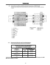
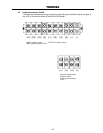
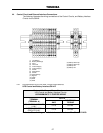
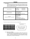
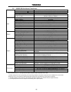
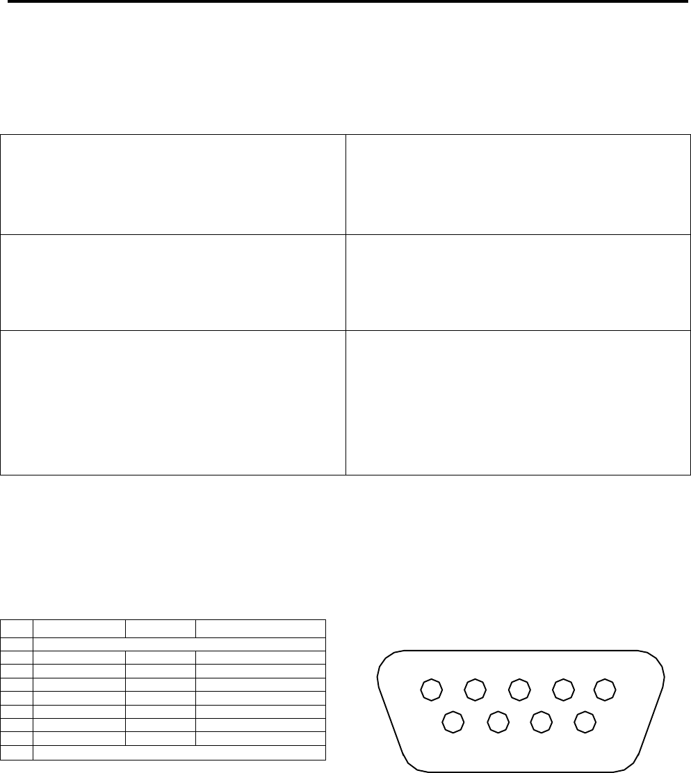
The connector pin assignment and female connector outline are illustrated below.
DB9 Female Connector Outline
(facing connector)
Pin I/O Symbol Description
1 This pin is not used
2 Input RXD Receive Data
3 Output TXD Transmit Data
4 Output DTR Data Terminal Ready
5 - SG Signal Ground
6 Input DSR Data Set Ready
7 Output RTS Request To Send
8 Input CTS Clear To Send
9 This pin is not used
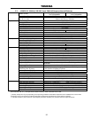
4.5.3 UPS Shutdown (via RS-232C)
When the UPS is operating from its internal batteries, a 'shutdown' order can be sent to the
UPS instructing it to turn OFF after a user-specified amount of time. This function can allow
you to stop discharging the UPS batteries after an orderly system shutdown has been
completed. The UPS can be programmed to turn OFF up to 8 minutes after the 'shutdown'
command is given. This command can be cancelled before the specified time has elapsed
by following the directions listed on the RS-232C screen.
5 4 3 2 1
9 8 7 6