


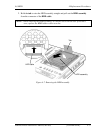

4.7 Slim select bay module 4 Replacement Procedures
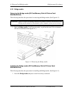
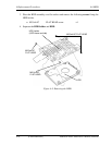
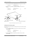
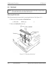
4. Remove the following screw and connector base from the optical drive assembly.
M2.03.0C S-THIN HEAD screw 2
5. Remove the following screws and ODD side assembly from the optical drive
assembly
M2.03.0C S-THIN HEAD screw 1
Rev D
M2.022.0C BIND screw 1
PORTÉGÉ M780 Maintenance Manual (960-809) [CONFIDENTIAL] 4-21
Figure 4-10 Detaching the optical drive assembly
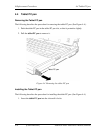
Installing the slim select bay module
The following describes the procedure for installing the slim select bay module. (See Figure
4-9 and 4-10.)
1. Install the ODD side assembly to the optical drive assembly and secure it with the
following screws.
M2.03.0C S-THIN HEAD screw 1
M2.022.0C BIND screw 1
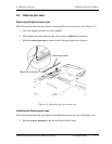
2. Install the connector base to the optical drive assembly and secure it with the
following screw.
M2.03.0C S-THIN HEAD
M2.03.0C S-THIN HEAD
M2.022.0C BIND
ODD side assembly
Connecto
r
Connector base