


2. MAJOUR UNIT REPLACEMENT EO18-33021
2.1. REPLACING THE CPU PC BOARD
2- 4
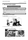
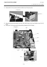
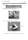
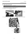
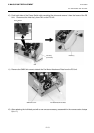
9) Remove the four screws (T-3x10 and SMW-3x6) and detach the CPU PC Board Ass’y from the Printer
Block.
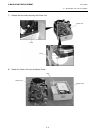
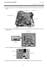
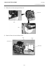
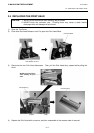
10) Remove the four screws (SMW-3x6 and P-3x6) and detach the CPU PC Board from the PC Board
Attached Plate.
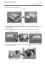
11) Remove the SMW-3x6 screw, N-3 Nut and Ground Plate.
12) Replace the CPU PC Board with a new one, and then reassemble in the reverse order of removal.
CPU PC Board Ass’y
T-3x10 Screw
Printer Block
T-3x10 Screw
SMW-3x6 Screw
T-3x10 Screw
P-3x6 Screw
SMW-3x6 Screw
N-3 Nut
Ground Plate
SMW-3x6 Screw