


2-6
EM18-33010A
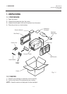
2. MAJOR UNIT REPLACEMENT
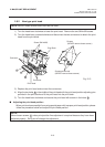
Fig. 2-10
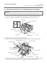
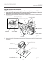
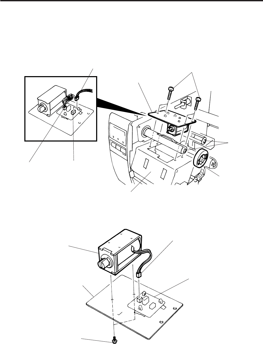
2.5 REPLACING THE SOLENOID
2.5 REPLACING THE SOLENOID
NOTE: The following procedure can be employed without removing the top cover and left side cover.
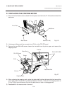
1) Before removing the ribbon stopper, check its attaching direction for later installation. Remove the
ribbon stopper from the ribbon shaft on which the ribbon is wound.
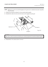
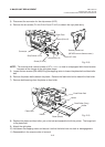
2) Remove the two SM-4x8B screws, disconnect the connector CN1 on the RSV PC board to detach
the solenoid unit.
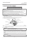
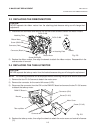
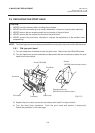
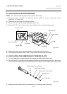
3) Remove the two SM-3x5B screws and disconnect the CN2 connector on the RSV PC board to detach
the solenoid.
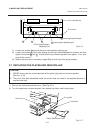
Fig. 2-11
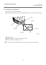
Ribbon Shaft
Ribbon Stopper
Print Block
RSV PC Board
CN2 (2 pin)
Connector CN1 (3 pin)
Solenoid Attaching Plate
Screw (SM-4x8B)
Solenoid
Connector CN2 (2 pin)
RSV PC Board
Screw (SM-3x5B)
Solenoid Attaching Plate