


28
G8000 Series Installation and Operation Manual (380 V)
11.1 120 and 180 kVA Buss Strip Terminals and Power Cables
Note: Always consult your site specic, local, state, and NEC electrical codes for wiring, cabling, and
circuit protection device requirements.
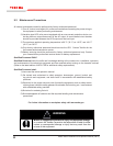
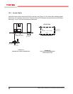
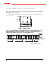
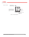
The 120 and 180 kVA UPS units have buss strip power terminals. Figure 11.2 is a typical buss strip for
a 120/180 kVA UPS.
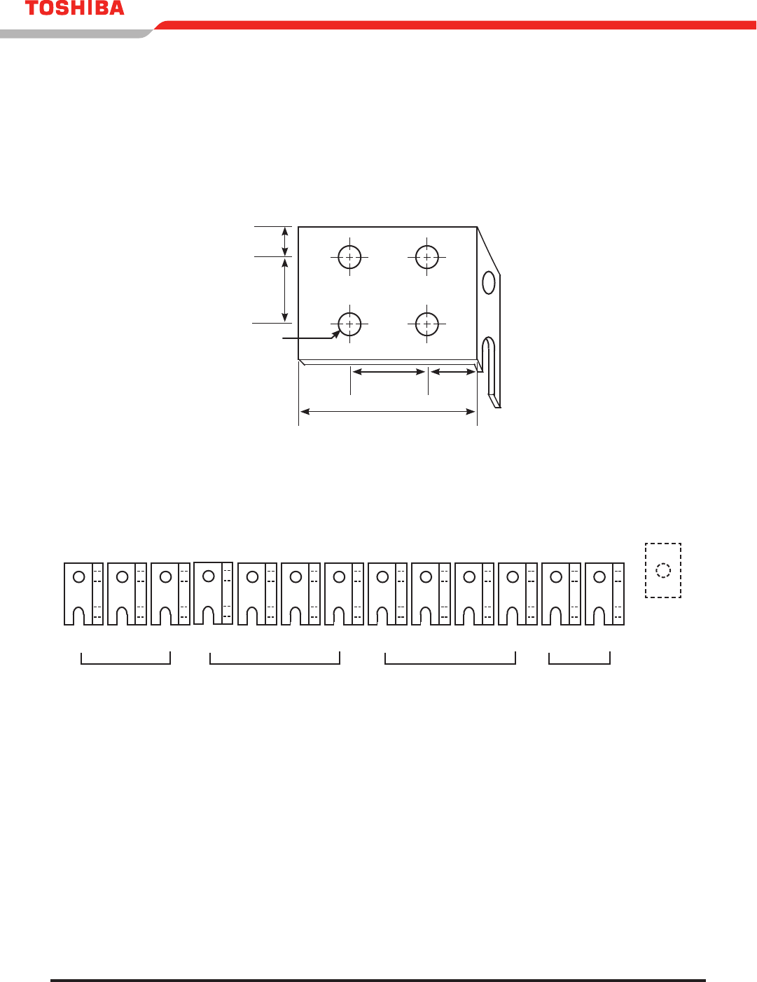
FIGURE 11.2 - TERMINAL BUS DETAIL
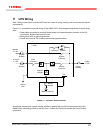
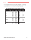
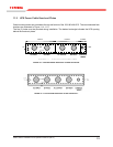
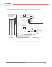
Figure 11.3 shows the arrangement of the terminal buss strips for the 120 and 180 kVA UPS units. The
terminal buss strips are located inside, at the bottom of the UPS. The dashed line on terminals 1–13
indicates the side view of the bolt holes. Use 1/2 inch bolts to attach the lugs.
FIGURE 11.3 - TERMINAL BUSS ARRANGEMENT FOR 120 AND 180 KVA UPS
5.3 in. (135 mm)
1.97 in.
(50 mm)
1.77 in.
(45 mm)
1.75 in.
(45 mm)
3 in.
(77 mm)
0.5 in. Dia.
(1.27 mm)
13
+
11
N
1
U
2
V
10
W
12
–
9
V
8
U
7
N
6
W
5
V
4
U
3
W
AC INPUT
AC OUTPUT
BYPASS INPUT
BATTERY
(Optional Flywheel
Input fuse. Flywheel (-)
connects to Battery (-))
Flywheel Input (+)
Note: Contact the factory if using more than one battery string,
ywheel, or combination battery and ywheel.