


31
G8000 Series Installation and Operation Manual (380 V)
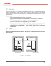
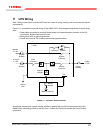
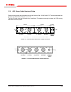
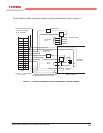
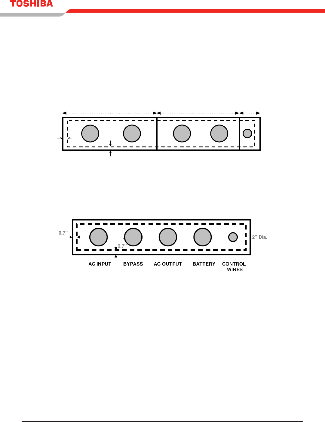
11.2 UPS Power Cable Knockout Plates
Cable knockout plates are provided at the top and bottom of the 120/180 kVA UPS. The recommended hole
locations are illustrated in Figure 11.4 - 11.5.
The ve (5) holes must be punched during installation. The dashed rectangle indicates the UPS opening
behind the knockout plates.
FIGURE 11.4 - BOTTOM CABLE KNOCKOUT PLATES 120/180 KVA
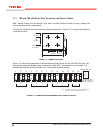
FIGURE 11.5 - TOP ACCESS KNOCKOUT PLATE 120/180 KVA -
G8000 Series Installation Manual
30
CONTROL
WIRES
0.8”
0.8”
2” Dia.
3” Dia.
AC INPUT
BYPASS
A
C OUTPUT
BATTERY
Plate #2
Plate #1
1 2 3 64 5 7 8 9 10 11 12
AC INPUT
3-phase 3-wire
BYPASS INPUT
3-phase 4-wire
BATTERY
AC OUTPUT
3-
p
hase 4-wire
U V W
- +
U V WVUNW
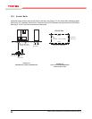
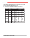
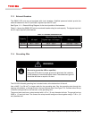
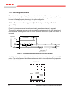
The cable knockout plates are provided at the bottom of each 100/150/225kVA UPS. The recommended
hole locations are illustrated in Figure 11.3 and 11.4.
The five (5) holes must be punched during installation. The dashed rectangle indicates the UPS opening
behind the knockout plates.
FIGURE 11.3 - CABLE KNOCKOUT PLATES100kVA (T80S3K10KK6XS2H
)
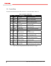
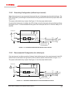
FIGURE 11.4 - CABLE KNOCKOUT PLATES
100kVA (T80S3K10KK6XSNH
); 150/225kVA
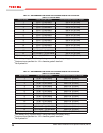
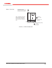
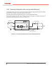
The terminal busses are located inside at the top of the 300kVA UPS. See Figure 11.5. The dashed line
indicates the side view of the bolt holes. Use 1/2 inch bolts to attach the lugs.
See Table 11.6 for recommended cable size and tightening torque for the 300kVA UPS. See Table 11.7
for vendor recommended lugs.
FIGURE 11.5 - TERMINAL BUSSES OF THE 300kVA UPS
0.4”
0.8”
4
”
Dia
.
2” Dia.
AC INPUT
BYPASS
AC OUTPUT
BATTERY
CONTROL
WIRES
Plate #1
Plate #2
Plate #3
PLATE #2 PLATE #3PLATE #1
4” Dia.