


4 Replacement Procedures
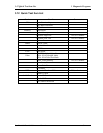
Figures
Figure 4-1 Removing the battery pack .................................................................................. 4-8
Figure 4-2Removing the battery pack .................................................................................. 4-9
Figure 4-3 Removing the PC card ....................................................................................... 4-10
Figure 4-4 Removing the memory cover ............................................................................. 4-12
Figure 4-5 Removing the optional memory......................................................................... 4-13
Figure 4-6 Removing the MDC cover ................................................................................ 4-15
Figure 4-7 Removing the MDC card .................................................................................. 4-16
Figure 4- 8Removing the wireless LAN card cover ............................................................ 4-18
Figure 4-9 Removing the wireless LAN card..................................................................... 4-19
Figure 4-10 Removing the HDD pack cover ...................................................................... 4-20
Figure 4-11 Removing the HDD pack................................................................................ 4-21
Figure 4-12 Removing the HDD chassis ............................................................................ 4-21
Figure 4-13 Removing the switch cover screw ................................................................. 4-23
Figure 4-14 Removing the hotkey board ............................................................................ 4-24
Figure 4-15 Removing the keyboard .................................................................................. 4-25
Figure 4-16 Removing the ODD bay module..................................................................... 4-27
Figure 4-17 Removing the ODD bay module..................................................................... 4-28
Figure 4-18 Removing the breaket from the ODD drive................................................... 4-29
Figure 4-19 Removing the screws from the bottom of the computer ................................. 4-30
Figure 4-20 Removing the display assembly...................................................................... 4-31
Figure 4-21 Removing the screws from the bottom of the computer ................................. 4-32
Figure 4-22 Removing the top cover .................................................................................. 4-33
Figure 4-23 Removing the speakers ................................................................................... 4-35
Figure 4-24 Removing the cooling module ........................................................................ 4-37
Figure 4-25 Applying silicon greases ................................................................................. 4-38
Figure 4-26 Removing the CPU .......................................................................................... 4-40
Figure 4-27 Installing the CPU............................................................................................ 4-41
Figure 4-28 Securing the CPU............................................................................................. 4-42
Figure 4-29 Removing the system board............................................................................. 4-43
Figure 4 -30 Removing the North Bridge thermal module.................................................. 4-45
4-vi Satellite A60/ Pro A60 Maintenance Manual