


4 Replacement Procedures
QOSMIO F10 Maintenance Manual (960-498) 4-v
Figures
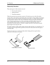
Figure 4-1 Removing the battery pack.................................................................................4-8
Figure 4-2 Removing the PC card .....................................................................................4-10
Figure 4-3 Removing the bridge media .............................................................................4-11
Figure 4-4 Removing the HDD assembly..........................................................................4-12
Figure 4-5 Removing the HDD..........................................................................................4-13
Figure 4-6 Removing the memory module........................................................................4-15
Figure 4-7 Removing the speaker cover assembly ............................................................4-17
Figure 4-8 Removing the keyboard ...................................................................................4-18
Figure 4-9 Removing the keyboard support plate..............................................................4-19
Figure 4-10 Removing the bluetooth module ......................................................................4-21
Figure 4-11 Removing the switch membrane ......................................................................4-22
Figure 4-12 Removing the optical drive assembly ..............................................................4-24
Figure 4-13 Disassembling the side bracket........................................................................4-25
Figure 4-14 Removing the screws (back) ............................................................................4-26
Figure 4-15 Removing the screws (front)............................................................................4-27
Figure 4-16 Removing the cables ........................................................................................4-28
Figure 4-17 Removing the display assembly.......................................................................4-29
Figure 4-18 Removing the wireless LAN antenna cables ...................................................4-30
Figure 4-19 Removing the SD board ...................................................................................4-33
Figure 4-20 Removing the MDC .........................................................................................4-34
Figure 4-21 Removing the fan.............................................................................................4-35
Figure 4-22 Removing the wireless LAN board..................................................................4-36
Figure 4-23 Removing the VGA fan cable ..........................................................................4-37
Figure 4-24 Removing the system board .............................................................................4-38
Figure 4-25 Removing the RTC battery..............................................................................4-40
Figure 4-26 Removing the TV tuner module.......................................................................4-41
Figure 4-27 Removing the guide .........................................................................................4-43
Figure 4-28 Removing the heat sink....................................................................................4-44
Figure 4-29 Removing the CPU..........................................................................................4-45