


4.10 Cover assembly 4 Replacement Procedures
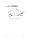
4.10 Cover assembly
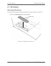
Removing the Cover assembly
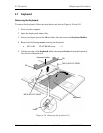
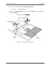
To remove the cover assembly, follow the steps below and refer to Figure 4-15 to 4-17.
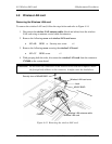
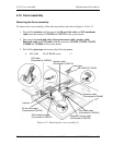
1. Peel off the insulator and disconnect the SD card slot cable and SW membrane
cable from the connector CN9720 and CN9721 on the system board.
2. Disconnect the touch pad cable, fingerprint sensor cable, speaker cable,
Bluetooth cable and LCD cable from the connector CN3240, CN9700, CN6170,
CN4400 and CN5000 on the system board.
3. Peel off the glass tape and remove the following screw.
• M2.5×6B FLAT HEAD screw ×1
LCD cable
(Connected to CN5000)
TECRA A8 /Satellite Pro A120 Maintenance Manual (960-573) [CONFIDENTIAL] 4-27
Figure 4-15 Removing the cover assembly (1)
Insulator
Fingerprint sensor cable
(Connected to CN9700)
Touch pad cable
(Connected to CN3240)
Glass tape
Speaker cable
(Connected to CN6170)
SD card slot cable
(Connected to CN9720)
SW membrane cable
(Connected to CN9721)
M2.5×6B FLAT HEAD
Bluetooth cable
(Connected to CN4400