


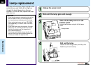
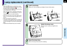
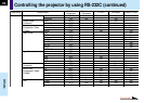
72
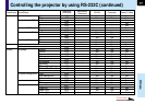
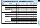
Others
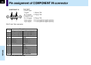
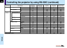
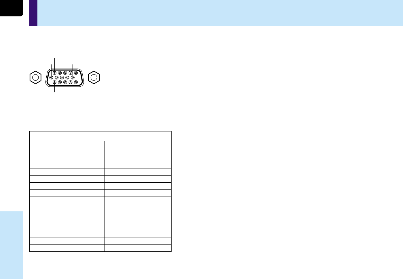
Mini D-sub 15pin connector
Pin assignment of COMPONENT IN connector
Input signal
• Y/PB/PR input
Y signal: 1.0V(p-p) 75Ω
PB, PR signal: 0.7V(p-p) 75Ω
• Computer input
R, G, B signal: 0.7V(p-p) 75Ω
H.sync signal: TTL level (positive/negative polarity)
V.sync signal: TTL level (positive/negative polarity)
Pin No.
1
2
3
4
5
6
7
8
9
10
11
12
13
14
15
Computer input
Video signal (Red)
Video signal (Green)
Video signal (Blue)
GND
GND
GND (Red)
GND (Green)
GND (Blue)
N.C
GND
GND
DDC2B data
H.sync signal
V. sync signal
DDC2B clock
Component input
Color difference signal (P
R
)
Luminance signal (Y)
Color difference signal (P
B
)
*
*
GND (PR)
GND (Y)
GND (PB)
*
*
*
*
*
*
*
Description
*
: Do not connect anything.
COMPONENT IN
51
10
1511
6