


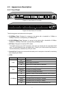
2.3 Appearance Description
2.3.1 Front Panel
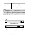
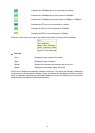
Figure 2-1 Front Panel of TL-SL3428
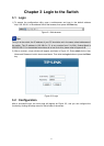
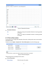
Figure 2-2 Front Panel of TL-SL3452
The following parts are located on the front panel:
10/100Mbps Ports: Designed to connect to the device with a bandwidth of 10Mbps or
100Mbps. Each has a corresponding 10/100Mbps LED.
10/100/1000Mbps Ports: Designed to connect to the device with a bandwidth of 10Mbps,
100Mbps or 1000Mbps. Each has a corresponding 1000Mbps LED.
SFP Ports: Designed to install the SFP module.
TL-SL3428 features some SFP transceiver slots that are shared with the associated RJ45
ports. The associated two ports are referred as a “Combo” port, which means they cannot be
used simultaneously, otherwise only SFP port works.
Console Port: Designed to connect with the serial port of a computer or terminal for monitoring
and configuring the switch.
LEDs
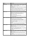
Name Status Indication
On Power is on.
Flashing Power supply is abnormal.
PWR
Off Power is off or power supply is abnormal.
On The switch is working abnormally.
Flashing The switch is working normally.
SYS
Off The switch is working abnormally.
On A device is linked to the corresponding port, but no activity.
Flashing Data is being transmitted or received.
Green The linked device is running at 100Mbps.
Yellow The linked device is running at 10Mbps.
10/100Mbps
Off No device is connected to the corresponding port.
7