


Getting Started Connections and Power
Trango Broadband Wireless — TrangoLINK-10 User Manual Rev. E 3.0 page 3
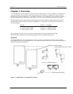
Chapter 2 Getting Started
First unpack your MU and RU. It is recommended that you first provision and test your the radios on the bench before
deploying them in the field. This is a particularly useful exercise for the novice user.
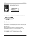
Connections and Power
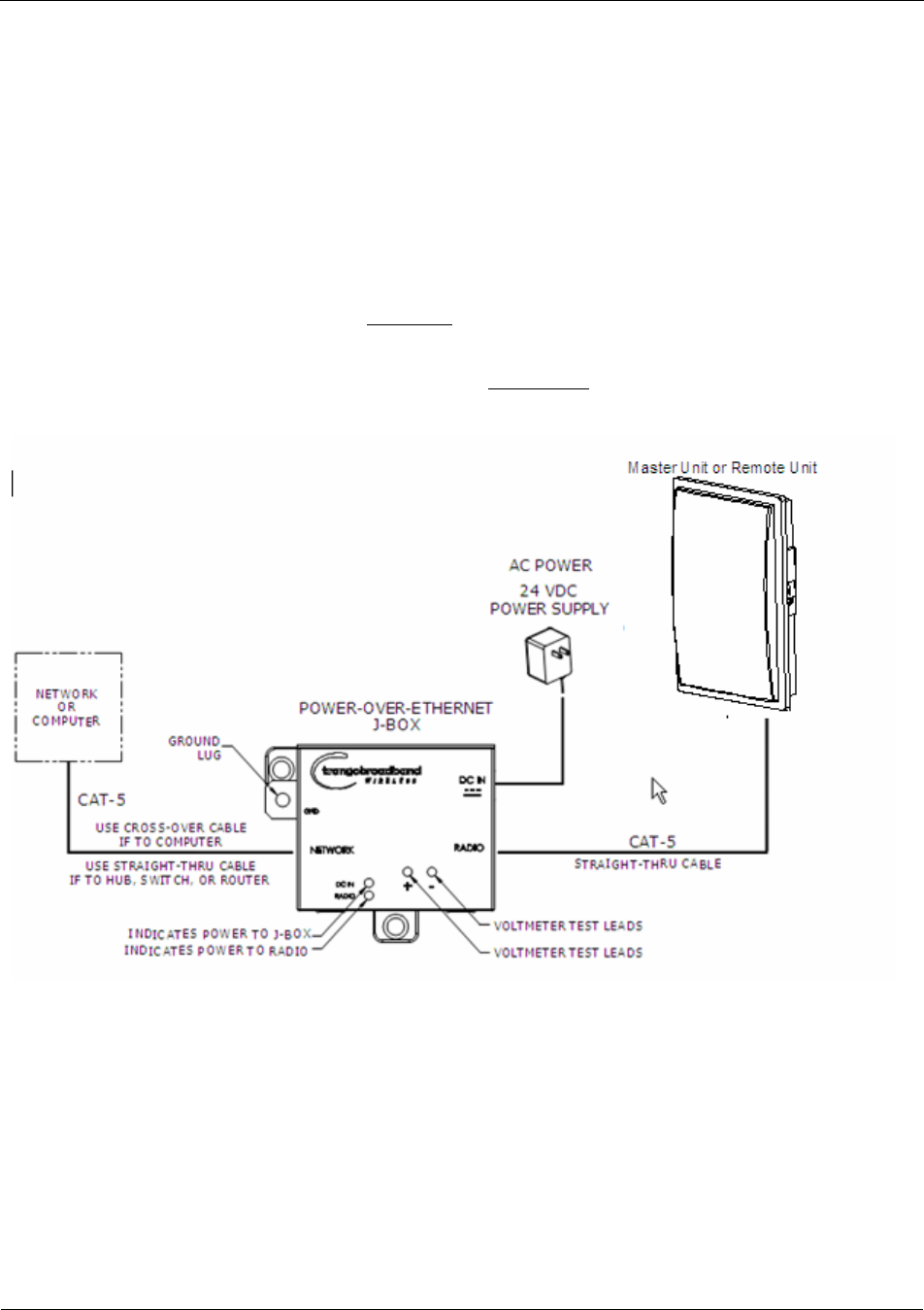
Connection and powering of the radios is the same for MUs and RUs.
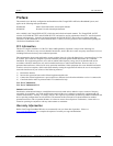
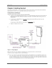
• Connect a Cat-5 (straight through) Ethernet cable (we recommend shielded twisted pair) between the ODU (out
door unit) port of the J-box and the RJ-45 connector on the radio. Note that this cable will carry power-over-
Ethernet (PoE).
• If connecting to a COMPUTER, use a Cross-Over
Ethernet cable from the NET port of the J-box to the
computer’s Ethernet port.
If connecting to a HUB, SWITCH, or ROUTER, use a Straight-Thru
cable.
• Plug the AC adapter into an AC outlet.
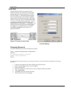
Figure 4: Wiring Diagram
Both green LEDs on the J-box should be lit, indicating power is present at the J-box as well as the radio.
You are now ready to configure the radio via the Ethernet port.
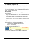
Note: If you cannot access the radio management functions via the Ethernet port, it is possible that your PC is not
set up with a properly routable subnet. If you forget the radio’s IP address, or for some other reason cannot access
the radio via the Ethernet port, use the Serial Programming cable (supplied with each TrangoLINK kit) and attach it
to the RJ-11 port located behind the access cover on the bottom of the radio.