4
1
2
3
4
5
6
7
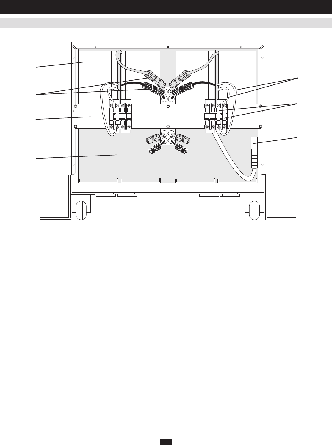
Individual models may vary slightly from diagram.
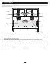
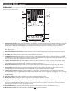
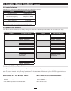
2.2 Battery Access Panel (Cover Removed)
2. Control Panels
(
continued
)
Internal Battery Packs: 1. Thesesupplybackupruntimetoconnectedequipment.Eachpackconsistsoftwostrings(onepositiveandonenegative).
ThenumberofincludedbatterypacksvariesdependingonUPSmodelnumber.Batterypacksmustreplacedbyaqualifiedelectrician.Note: The
UPS system ships with the internal batteries disconnected. Refer to the Adding or Replacing Internal Batteries section for battery connection
instructions.
Battery Cartridge Fuses: 2. Protectagainstshortcircuitdamage.Ifaheavyoverloadorshortcircuitisencountered,afusewillblow.Abatterypack
withablownfusewillnotdeliveranyoutputvoltagetotheUPSsystem.Thefusesmustbereplacedbyaqualifiedelectrician.(Seesection7,
Adding or Replacing Internal Batteriesfordetails.)
Internal Battery Pack Connectors (Red & Black):3. Connect the individual internal battery packs to the overall battery system.
Internal Battery Pack Jumper Cables (White & Blue):4. Connect the internal battery pack strings together through the fuse block.
Battery System Connectors: 5. Oneconnector(internal,notshown)connectsthebatterymoduletothepowermodule.Theotherconnector(shown)
connectsthebatterymoduletoanadditionaloptionalbatterymodule(notshown,availableseparatelyfromTrippLite).Thebatterysystem
connectorsareonlyutilizedwhenaddinganadditionalbatterymodule.Useoftheseconnectorsisoutlinedintheowner'smanualincludedwiththe
additional battery module.
Extended Runtime Capability:6. Openslotsacceptadditionalinternalbatterypacks(availableseparatelyfromTrippLite)toextendruntime.The
numberofopenslotsvariesdependingonUPSmodelnumber.Allmodelsaccepttheconnectionofanadditionalbatterymodule(available
separatelyfromTrippLite)tofurtherextendruntime.ContactTrippLitefordetails.
Fuse Block Bracket:7. Accepts battery cartridge fuses.


