


6
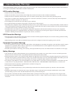
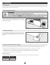
Move your UPS over short distances using its wheels. Note: The wheels are not designed to provide long-term support for the UPS system after final
installation. Mounting bracket installation is required.
DANGER!
RISK OF PRODUCT DAMAGE AND SERIOUS PERSONAL INJURY
The UPS System's wheels are not designed to provide long-term support for the UPS system after final
installation. Mounting bracket installation is required. If the mounting brackets are not installed, the
wheels may eventually fail and potentially damage the UPS System and cause serious personal injury.
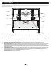
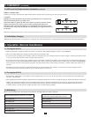
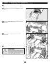
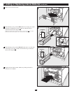
Usingtheincludedbolts,installonemountingbracketoneachsideofthe
UPSSystemasshown.Ifdesired,installthebrackettothefloorsurface
with user-supplied hardware.
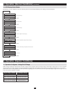
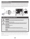
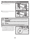
Using a user-supplied 4AWG ground wire, connect the UPS System's
groundlugtoearthground.Tightenconnectionswithatorqueofnotless
than35inch-lbs.(3.9NM).Keepgroundwireconnectedatalltimesafter
installation.
Warning: When installing the unit, verify that any maintenance bypass panel used is configured correctly before applying power to the unit.
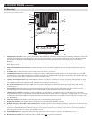
Inadditiontotheinstructionslistedbelow,followallwarningsfoundinsection1,Important Safety Warnings,priortoconnection.
• InstallwithflexcableofsufficientlengthtomoveUPSclearofsurroundingequipmentforservicing(sidesandrear).
• UseferrulecapstocoverterminationcablesconnectedtoUPStoavoidfrayedendsfromshortingonterminalblock.
• Neutralconductormustbesamesizeascurrentconductors.
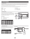
WIRING SELECTION
Choose appropriate cabling (ratedVW-1,FT-1orbetter)toconnectyourUPStoanACpowersupplyandyourequipment.
UPS System Model Wiring Size
20kVA 6AWG/14mm
2
30kVA 4AWG/22mm
2
MaximumCableLength:10m(32.8ft)
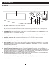
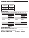
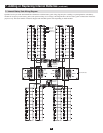
Front View
Rear View
3.2 Mounting Bracket Installation
3.3 Grounding Connection
3.4 UPS Input And Output Hardwire Connection
3.1 UPS Location
3. Installation