


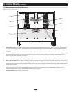
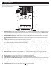
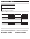
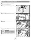
Individual models may vary slightly from diagram.
5
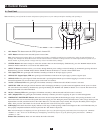
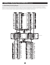
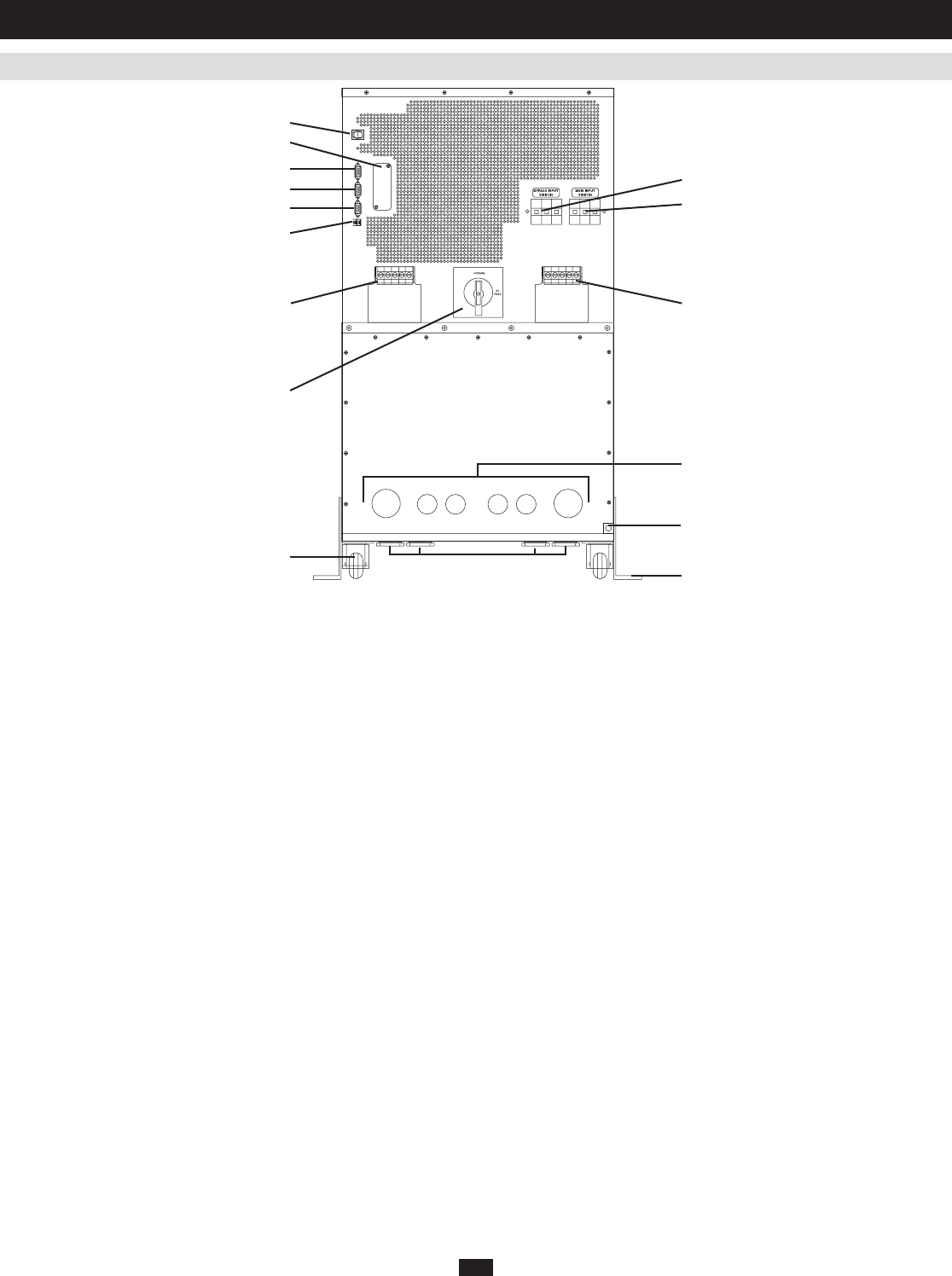
Manual Bypass Switch:1. ThisdialisusedtoputtheUPSin“BYPASS”mode,whichmustbedonebeforeperforminganymaintenanceontheUPS
withtheconnectedloadsupported.(Seesection5,Operation (Special Conditions),forstep-by-stepinstructionsforgoinginto“BYPASS.”)While
thisswitchison“BYPASS,”connectedequipmentwillreceivefilteredACmainspower,butwillnotreceivebatterypowerintheeventofa
blackout.
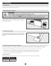
Input Terminal Block (cover removed):2. Use these terminals to connect your UPS to the AC main power input. Unscrew and remove terminal
block plate for access.
Output Terminal Block (cover removed):3. UsetheseterminalstoconnectyourUPStoequipment.Unscrewandremoveterminalblockplatefor
access.
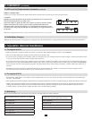
Grounding Lug:4. ConnectstheUPSsystemtoearthground.(Seesection3,Installation.)
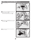
AS-400 Interface Port:5. ThisfemaleDB9portconnectsyourUPStoanIBMAS-400computerinterfaceviaanAS-400Cable.ItusesAS-400
communicationstoreportUPSstatusandpowerconditions.Usingthisport,anIBMAS-400computercanautomaticallysaveopenfilesandshut
downitsoperatingsystemduringablackout.(Seesection6,Communications.)
“Smart” RS-232 Interface Port:6. ThisfemaleDB9portconnectsyourUPStoaworkstationorserver.ItusesRS-232communicationstoreport
UPS and power conditions. It is used with Tripp Lite software and an RS-232 Cable to monitor and manage network power and to automatically
saveopenfilesandshutdownequipmentduringablackout.(Seesection6,Communications.)
Dry Contact Interface Port:7. ThisfemaleDB9portsendscontact-closuresignalstoindicateline-failandlow-batterystatus.(Seesection6,
Communications.)
Accessory Slot:8. Remove the small cover panel and use optional accessories to remotely control and monitor your UPS. Contact Tripp Lite
CustomerSupportformoreinformationandalistofavailableSNMP,networkmanagementandconnectivityproducts.
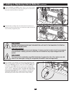
“Battery Start” Switch:9. Thismomentaryrockerswitchallowsyouto“cold-start”yourUPSanduseitasastand-alonepowersourcewhen
utility-suppliedACpowerisnotpresent.TheswitchenablestheUPS’sDC/ACInverter.Before“cold-starting”yourUPS,makesureitisproperly
installed.Pressandholdthe“BatteryStart”Switchandthenpressthe“ON”buttontoturnyourUPSON.ToturnitOFFafter“cold-start,”press
the“OFF”button.
Main Input Switch:10. Circuit breaker controls AC input power to the UPS during normal operation.
Bypass Input Switch: 11. CircuitbreakercontrolsACinputpowertotheUPSduring“BYPASS”operation.
Remote “Emergency Power OFF” (EPO) Connector:12. Thismodularjackallowsremoteemergencyshutdown.(Seesection6,Communications.)
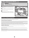
Wheels: 13. Thewheelsareonlydesignedforslightpositionadjustmentswithinthefinalinstallationarea;theyarenotdesignedformovingtheUPS
System over considerable distances. Note: The wheels are not designed to provide long-term support for the UPS system after final installation.
Mounting bracket installation is required. See Installation section.
Mounting Brackets: 14. Help support the UPS system. Note: Mounting bracket installation is required. (See Installation section.)
Hardwire Access Points: 15. Allow either back panel or bottom panel access for electrical connection.
1
3 2
4
5
6
7
8
9
10
11
12
13
14
15
15
2.3 Rear Panel
2. Control Panels
(
continued
)