8
Installation
Standard Installation
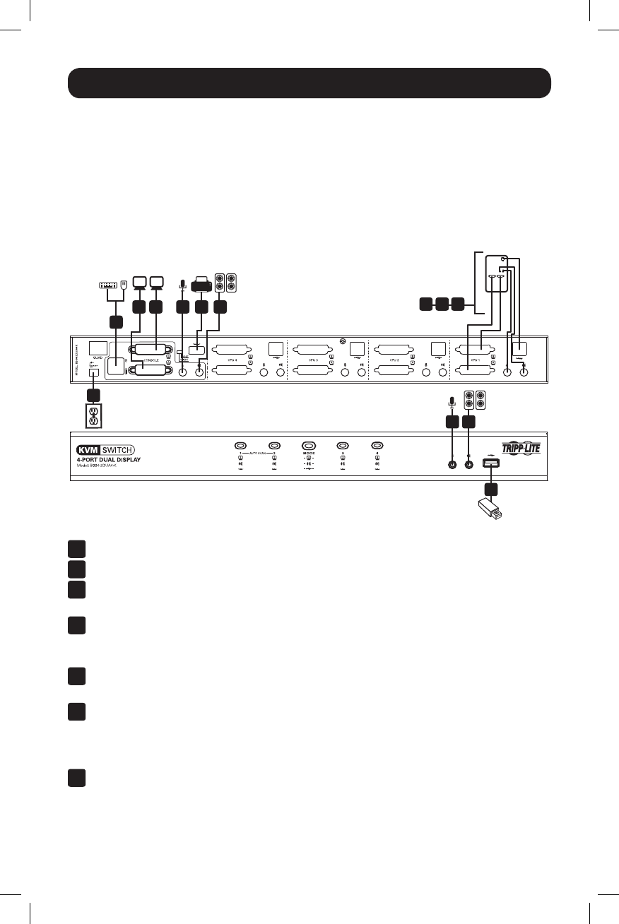
RefertothefollowingstepsanddiagramtosetupyourKVMswitchinstallation.
Notes:
1. Before making any connections, make sure that power to all devices being connected to the KVM switch is
turned off. Unplug the power cords of any computers that have the Keyboard Power On function.
2. The diagram below shows the B004-2DUA4-K installation. Installation for the B004-2DUA2-K is the same
except there are fewer ports.
1 2 4
4 4
4
10
5
5
3
1
ConnectamonitortotheDVIconsoleAportonthebackpaneloftheKVMswitch.
2
ConnectamonitortotheDVIconsoleBportonthebackpaneloftheKVMswitch.
3
ConnectaUSBkeyboardandmousetothecorrespondingUSBkeyboardand
mouseconsoleportsonthebackoftheKVMswitch.
4
Optional – Connectyourmicrophoneandspeakerstothecorresponding3.5mm
MiniStereoconsolejacksonthefrontpanelorthebackpanel.Thejacksonthe
frontpaneloftheunitwilltakepriorityoverthoseonthebackpanel.
5
Optional – ConnectyourUSBdevice(s)totheUSB2.0hubport(s)onthefrontand
backoftheKVMswitch.
6
ConnecttheendoftheKVMCableKitthatincludestheUSBTypeBMaleconnector
toanavailablesetofcomputerportsonthebackpaneloftheunit.Connectthe
DVIconnectortotheDVIAport,andtheUSBand3.5mmconnectorstothe
correspondingUSBand3.5mmports.
7
ConnecttheotherendoftheKVMCableKittothecorrespondingportsonthe
computer you wish to add to the installation. Note:TheB004-2DUA2-Kand
B004-2DUA4-Kcomewith6ft.CableKits.Ifyouneedalongercable,youwill
havetopurchaseaseparateP759-SeriesDVI/USB+AudioKVMCableKitofthe
appropriate length.
86 7
13-09-063-933242-EN.indd 8 9/10/2013 4:45:01 PM


