


1
Yourmodelmaydiffer.
2a
2b
2c
Yourmodelmaydiffer.
Yourmodelmaydiffer.
13
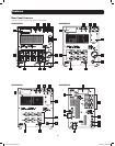
Basic Connection and Start-Up
Optional Connections
YourUPSwillfunctionproperlywithouttheseconnections.
1
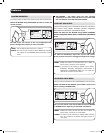
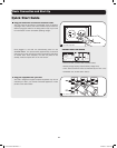
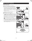
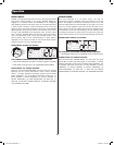
Phone Line or Phone/Network Line Surge Suppression
YourUPShasjackswhichprotectagainstsurgesonaphoneline.
Select models feature jacks which also protect against surges on
a network line.* Using appropriate telephone or network cords
connect your wall jack to the UPS jack marked “IN.” Connect your
equipment to the UPS jack marked “OUT.” Make sure the
equipment you connect to the UPS's jacks is also protected
against surges on the AC line.
* Not compatible with PoE (Power Over Ethernet) applications.
Note: Use the same type of connector for the phone line surge suppression input and
output ports.
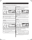
2
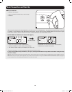
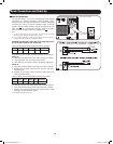
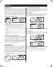
USB and RS-232 Serial Communications
Use the included USB cable (see
2a
) and/or DB9 serial cable
(see
2b
) to connect the communication port of your computer
to the communication port of your UPS. Install on your computer
theTrippLitePowerAlertSoftwareappropriatetoyourcomputer's
operating system. Your UPS may feature additional
communications ports; these ports may be connected to
additional computers that have PowerAlert Software installed.
Consult your PowerAlert manual for more information.
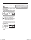
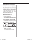
2c
Dry contact communications are simple, but some knowledge
of electronics is necessary to configure them. The DB9 port’s pin
assignments are shown in the diagram. If the UPS battery is low,
the UPS sends a signal by bridging pins 1 and 5. If utility power
fails,theUPSsendsasignalbybridgingpins8and5.Toshut
theUPSdownremotely,shortpin3topin9foratleast3.8
seconds. It takes approximately 1 minute for the UPS to shut
down after shorting pin 3 and pin 9.
13-03-138 93-3168-EN.indd 13 3/28/2013 1:05:16 PM